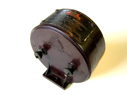
All American Filter Transformer Type R-120
The All American brand IF transformers date from about May 1924, and, like many of the early transformers, they were designed to operate at 30 KC. The model R-120, investigated here, was the air-core filter transformer of the series. What is a filter transformer? The filter transformer is a sharp peaking or narrow bandpass transformer. Early superhets usually had two or three non-filtered transformers and one filter transformer, but that wasn’t a given rule. Some designs used two of each type in an alternating fashion. The design of the IF amplifier and the IF transformers was the greatest debated topic of the early superhet.
Air-core, iron-core, low frequency, high frequency, filter transformer before the non-filtered transformers, filter transformer after the non-filtered transformers, etc., were the hot topics of the day. Air-core transformers generally peaked much sharper than iron-core transformers. Because of the alignment problem, cascading several stages of a sharp peaking transformer was much more difficult than cascading several stages of a wider bandwidth transformer. Most experimenters recommended using several stages of the iron-core transformer to get the RF gain needed, and then just use one stage of the air-core transformer to get the desired selectivity from the entire chain.


All American type R-120 filter transformer.
Selectivity seemed to be a prime objective over all other factors in the early superhets. Selectivity is the term used to describe how a set receives one signal and rejects adjacent signals. The main desire for everyone in the early days was to cut through the strong local stations and snag a weak station located some 2000 miles away. To increase the selectivity the bandwidth needs to decrease. There’s a problem here, though, that many of the early experimenters did not understand. A radio signal is composed of sidebands, and the sidebands store the fidelity of the transmitted signal. This means that the bandwidth of the IF amplifier should be wide enough to pass the audio frequencies of voice and music. Selectivity and bandwidth are apposing factors; increase one and you decrease the other.
The design of the All American R-120 filter transformer was probably aimed more towards selectivity rather than fidelity. The primary and secondary coils of the transformer have a low resistance, and the secondary coil is shunted with a capacitor. The result is a relatively high-Q circuit with a correspondingly narrow bandwidth. The R-120 transformer has one of the narrowest bandwidths I have measured. A set built with this type of transformer will have razor sharp selectivity. This is the reason why many of the early superhets required vernier tuning controls (especially for the oscillator control). The sharp selectivity comes at the cost of reduced audio frequency response.
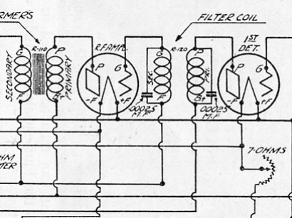
The R-120 transformer comes apart easily after removing a few screws. The photo below shows the interior view of the transformer. The primary coil is on the left and the secondary coil and its capacitor are on the right. My R-120 transformer is very different than the one shown in schematic diagram of the Fall 1924 Citizens Radio Call Book. The primary and secondary coils on my transformer are wound with different sizes of wire and only the secondary coil has a capacitor. The primary inductance is 2.39 mH, the secondary inductance is 24.7 mH, and the secondary capacitor is a .001 mfd (it measures .00136 mfd).

All American type R-120 transformer inside view.
As mentioned before, the gain and bandwidth of an IF amplifier stage is controlled by the bias voltage on the return of the secondary winding of the IF transformer. In most of the early superhets the return of the secondary winding went to the wiper of a 400 ohm potentiometer. One end of the potentiometer was connected to A- and the other end of the potentiometer was connected to A+. The bias voltage could therefore be adjusted anywhere between A- and A+. The 400 ohm potentiometer was used as a volume control and it was often identified on the front panel as “Potentiometer,” “Pot,” or “Volume.” The table below shows the difference in the frequency response when the secondary of the transformer is referenced to A- and A+. In actual operation it would be somewhere between the two extremes.
.
|
Type |
Peak Freq. |
Lower 3 dB |
Upper 3 dB |
Bandwidth |
Relative gain |
Pri. ohms |
Sec. ohms |
|
Filter, R-120 A- bias |
28.6 KC |
27.8 KC |
29.5 KC |
1.7 KC |
9.6 |
1.4 |
19.8 |
|
Filter, R-120 A+ bias |
28.8 KC |
23.6 KC |
34.7 KC |
11.1 KC |
1.4 |
1.4 |
19.8 |
Diagram from the Fall, 1924, Citizens Radio Call Book.