Armstrong Super-Heterodyne
|
Armstrong Super-Heterodyne |
 |
 |
|
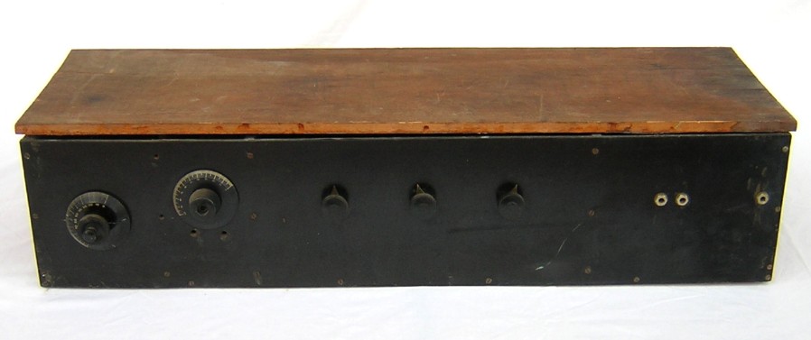
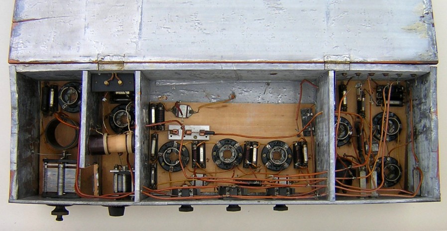
A few years ago a gentleman from Texas (Mike) sent me some photos of a bunch of old superhets that he had recently acquired. There were many desirable sets among the lot, including a few Leutz’s, a few Scott’s, a Pressley, a Receptrad, a St. James, and a Lincoln. One photo showed a miscellaneous lot of some thirteen or fourteen sets stacked five or six high. Of particular interest to me was a very early set that he said was made by a Signal Corps veteran of World War 1. Everything about this set had a primitive look to it, as far as tube radios go, including the early 3-inch tuning dials, the porcelain RCA tube sockets, the RCA audio transformer, the tinfoil shielded compartments, and the wiring. Most of all, it looked like the IF amplifier was resistance coupled! |
|
|
In February, 2015, I got an unexpected e-mail from Mike inquiring if I was still interested in the old “home-brew.” “Are you kidding?” Yes, I was definitely still interested in it, and a deal was soon made. It took a few weeks to get it in the mail. It was well packed and double boxed, and it actually took over an hour to remove the outer layers of the packaging. What was left was the radio heavily wrapped in plastic wrap lying on the floor of my radio room. It was late and I was exhausted, so I decided to “savor the moment,” and open it up the rest of the way in the morning. I had waited over a year to get my hands on this radio and a few more hours wouldn’t hurt. |
|
 |
|
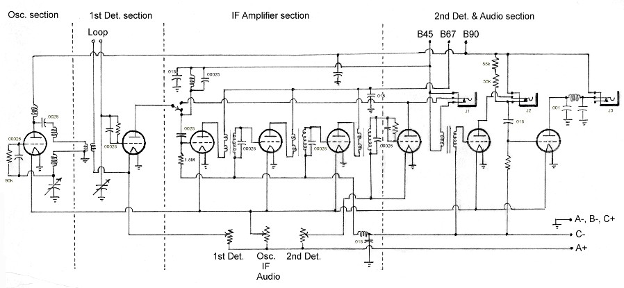
Hand-drawn schematic diagram of the early superheterodyne. It’s got a few design features that I’ve never seen before. The entire oscillator section is unusual, but mostly in the way the energy is coupled into the 1st detector. The tuned circuit for the 1st detector plate resistance is very unusual and the 1st detector is resistance coupled to the first IF stage. I believe the switch is used to couple the output of the 1st detector directly into the audio amplifier. The IF transformers are unusual. Note that the grid bias of the first three IF stages is de-coupled with a choke and bypass capacitor and is connected directly to C-. This set does not have the usual stability control for the IF amplifier. Perhaps the only way to control the IF gain is to adjust the filament voltage. The LC filter on the audio output is unusual. I think most of the set is deigned very well. Feedback and oscillations are controlled with the separate shielded compartments and good de-coupling of the various power supply feeds. |
|
|
Here are a few specifics about the set: 1. The radio works on the standard 1920s superhet scheme. |
|
 |
|
Close-up view of the IF amplifier. The transformers are identified on the baseboard with a “no I” for the first transformer, a “no II” for the second transformer, and a “no III” for the third transformer. Not visible in the photos, but the tuning capacitor for each transformer has a paper label on the underside that identifies it the same way as the transformer. Many of the parts throughout the set are identified with pen or pencil on the baseboard. |
 |
|
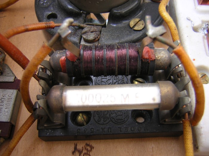
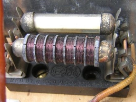
Close-up view of the “no I” IF transformer and associated tuning capacitor. I thought that the transformers were resistors when I fist saw photos of the set. The secondary coil is divided into five different sections and it is sandwiched between two different primary coils (each primary coil is connected in series and they are located on each end of the assembly). I believe the sectional construction was to reduce the distributed capacitance of the coils. The wire is very fine and the coil assembly is attracted to a magnet (indicating that it has some type of an iron core). The transformer would have a relatively small external magnetic field and it would be a good choice for a multistage amplifier. |
 |
 |
|
Above left: close-up photo of the 1st detector plate tuned circuit. This coil, or choke, is similar to the IF transformers, but there is only one coil. Like the IF transformers, it is shunted with a .00025 mFd capacitor. |
 |
 |
|
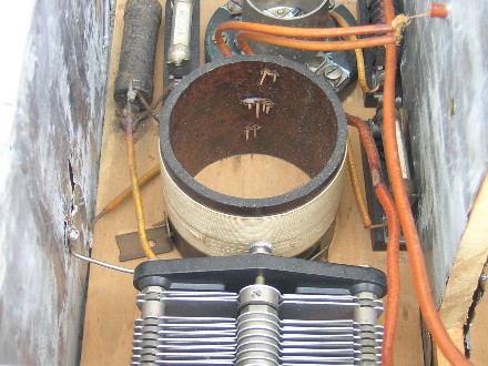
Above left: Close-up view of the oscillator coil and associated components. The grid bias resistor is the large black cylinder in the upper left corner. |
 |
|
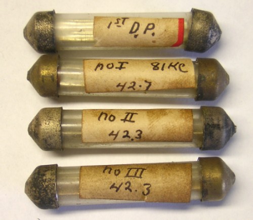
Photo showing the labels on the 1st detector plate tuning capacitor and the IF transformer tuning capacitors. The capacitors are all .00025 mFd and they all measured very close to the rated value. Capacitor number 1 (no I) is marked with a frequency of 81 KC. I don’t exactly know what the other numbers mean but it was obviously an attempt to match the frequency on the different transformers. The builder of this set had access to some type of measuring equipment. The 1st detector plate coil had a similar label attached to it but the label was loose in the bottom of the set when I got the radio. |
 |
|
Photo showing the 2nd detector and audio amplifier. The 2nd detector grid leak bias is in the upper left corner, the audio output filter is in the upper right corner. |
 |
 |
|
Above left: Close-up photo of the first audio plate resistors. Each resistor is 55k ohms, giving a total load resistance of 110k ohms. I am not familiar with this type of resistor. The oscillator bias resistor is the same type of construction. |
 |
|
This is a scan of an old piece of paper that was found lying in the bottom of the radio. Some of the parameters on the left column include the 2nd audio, 1st audio, 1st RF, 2nd RF, 3rd RF, 1st detector, 2nd detector, and oscillator. Other parameters may indicate different experiments. Most of the data looks like plate current measurements at 45 volts and 90 volts. In the upper right corner it looks like the words Reflected & Forward. This paper shows evidence of extensive experimenting with the radio. I like this type of documentation on a radio; I just wish the author would have put his name and date on it! |
|
Below is a table showing the bandpass properties of the different stages in the IF amplifier. The grid bias on the first three stages was referenced to A-. The grid bias on the last stage was referenced to A+ and the grid leak components were in the circuit. |
|
|
* this transformer actually had two peaks, the largest peak at 77.4 KC, and a smaller peak at 81.0 KC. This was the only transformer that showed two peaks. |
 |
||||||||||||||||||
|
Radio Corporation of America advertisement from the August, 1921, Pacific Radio News magazine. This one advertisement has three of the major components used in my early superheterodyne! The tube socket shown in this ad is probably of a newer design than the tube sockets in my radio. The UV-712 transformer was advertised as being introduced in July, 1921, so my early superhet must have been made sometime after July, 1921. |
||||||||||||||||||
|
I searched through many early magazines trying to find information on the IF transformers used in this superhet. Another goal of the research was to look for similarities in circuit design and try to pinpoint a date of manufacture. The following is a chronological list of the different articles found, and information specific to this set. The various magazines can be found online for viewing and download at AmericanRadioHistory.com Edwin H. Armstrong gave a talk about the superheterodyne at Columbia University on December 19, 1919. For many people this was probably the first news that they had ever heard about the new system for short-wave reception. Within two months of this talk there were three different articles published in national magazines describing the superheterodyne, and giving enough details for experimenters and amateurs to make one! |
||||||||||||||||||
|
(1) 1920, Feb., QST, A New Method for the Reception of Weak Signals at Short Wave Lengths, by Edwin H. Armstrong, E. E. |
||||||||||||||||||
 |
||||||||||||||||||
 |
||||||||||||||||||
|
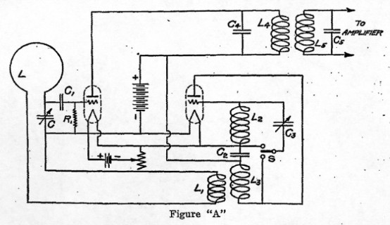
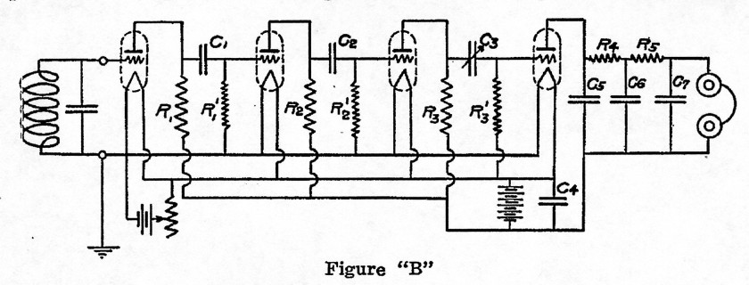
The above two diagrams were included in Armstrong’s article in the Feb., 1920, QST, as an addendum from the Hartley Research Laboratory at Columbia University (Armstrong’s laboratory). This diagram is typical of most resistance coupled superhets. The tuned input coupler, C4 & L4, and C5 & L5, provided selectivity for the IF amplifier, as the resistance coupled amplifier itself is fairly wide banded. I believe the variable capacitor C3 in Figure B was used as a stability control. Of particular interest to my set is the RC filter on the audio output. The filter is similar to the filter used in my set, and it was used keep the radio frequency currents out of the telephone cords and prevent their reaction on the input of the amplifier and thus prevent oscillations. |
||||||||||||||||||
|
(2) 1920, Feb., The Wireless Age, High Amplification at Short Wave Length, by Paul F. Godley |
||||||||||||||||||
|
(3) 1920, Feb., Radio News, The Armstrong Super-Autodyne Amplifier, Part 1, by H. W. Houck |
||||||||||||||||||
|
(4) 1920, March, Radio News, The Armstrong Super-Autodyne Amplifier, part 2, by H. W. Houck |
||||||||||||||||||
 |
||||||||||||||||||
|
Schematic diagram from the Houck article in the March, 1920, Radio News magazine. This circuit is somewhat similar to my early superhet in that the secondary of each RF transformer is shunted with a capacitor (most of fixed value). I believe the variable capacitor C2 in the IF amplifier is used as a stability control; de-tune to the point where the amplifier stops oscillating. |
||||||||||||||||||
|
(5) 1921, Aug., QST, Reception of 200-meter Signals by Means of a Loop and an Armstrong Super-Heterodyne, by Leroy M. E. Clausing It is interesting to note that this article is one of the first published since the first four articles were published in February/March of 1920. That is nearly one and a half years. |
||||||||||||||||||
|
(6) 1921, Dec., Radio, The Armstrong Super-Heterodyne, by A. K. Aster |
||||||||||||||||||
|
(7) 1922, Jan., Radio News, -and now 200 meter Radio Frequency Amplification |
||||||||||||||||||
|
(8) 1922, Feb., QST, Official Report on the Second Transatlantic Tests, by Paul F. Godley |
||||||||||||||||||
|
(9) 1922, Feb., Radio, Construction of a Radio Frequency Amplifier from Standard Parts, by G. M. Best |
||||||||||||||||||
|
(10) 1922, July, Wireless Age, Models built from Experimenters Information Service Blue Prints |
||||||||||||||||||
|
(11) 1922, Oct. 7, Radio World, Superheterodyne Receiver as Applied to the Armstrong Superregenerative Circuit, by Charles R. Leutz |
||||||||||||||||||
|
(12) 1922, Dec., Wireless Age, A Practical Super-Heterodyne Receiver, by 2ZL Station (also 2XAQ), editor |
||||||||||||||||||
|
(13) 1923, Feb., Radio Broadcast, A Super-Sensitive Long Range Receiver, by Paul F. Godley |
||||||||||||||||||
|
(14) 1923, June, Popular Radio, Question: Please show me a hook-up of an Armstrong super-heterodyne receiver |
||||||||||||||||||
|
(15) 1923, July, Radio News, Super-Heterodyne Receiver, by R. R. Mayo |
||||||||||||||||||
|
(16) 1923, July, Radio News, For Long Distance Concerts Super Heterodyne; New Advanced Model “C” |
||||||||||||||||||
|
The year 1923 ended up with several more superhet articles, including the Roberts from the Aug. Radio Broadcast (UV-1716 transformers), the Haynes-Griffin from the Sept., Oct., Nov., and Dec. Popular Radio (Haynes-Griffin air-core transformers), the Eltz from the Nov. Radio Broadcast (UV-1716 transformers), the Pearne from the Nov. Radio Age (probably UV-1716 transformers), and the de Willy & LaCault from the Dec. Radio News (UV-1716 transformers). So, where does my early superheterodyne fit in the scheme of things? My set was made almost exclusively with RCA parts, and if the RCA UV-1714 and UV-1716 transformers were available then I’m sure the builder would have used them. My set must predate the RCA transformers, or at least predate the time that those transformers were easily procured. |
||||||||||||||||||
 |
||||||||||||||||||
|
Advertisement for the Radio Instrument Company Type DX radio frequency transformer, as copied from the December, 1921, Radio News magazine. “It uses an iron core. The unique design (patent pending) eliminates capacity effects. Close electromagnetic coupling.” The transformers in my set could easily be described that way. My transformers could easily fit inside the rectangular box of the DX type transformer. |
||||||||||||||||||
 |
||||||||||||||||||
|
Major Edwin H. Armstrong, circa 1918 |
||||||||||||||||||
|
This page was added to this site on April 10, 2015 |
||||||||||||||||||
|
January 31, 2017 update: |
||||||||||||||||||
|
Mike from Texas sent me an e-mail and informed me that Les Miller (from San Antonio) was the guy that made this radio. It is great to know the name of the guy that made the radio and it gives a new direction for research. Speaking of research, I’ve just about decided that the intermediate frequency transformers in this radio are not the Radio Instrument Company types after all. The Radio Instrument Company “DX” type transformers are wound similar to the transformers in this radio (six machined slots for the primary and six machined slots for the secondary), but instead of having the secondary sandwiched between the primary, as the IF transformers in my radio, the “DX” type transformer has the primary and secondary at opposite ends of the former. The “DX” type transformer uses very fine wire for the coils, but the transformer is square and much larger than the transformers in this radio. I believe the IF transformers in this radio predate the Radio Instrument Company transformer (as advertised in the December, 1921 Radio News magazine). Click HERE for more information on the construction of the Radio Instrument Company transformer. Percival Lowell invented the type of transformer construction as used by the Radio Instrument Company, but he did not originate the idea of an iron core radio frequency transformer. Captain H. J. Round in England was working with air core transformers wound with very fine wire in about 1916, and about the same time Marius Latour in France was working with iron core transformers wound with very fine wire. The objective of their research was to develop a wide band radio frequency amplifier that did not need tuning adjustments for the various stages of the amplifier. To reach this objective it was desirous to increase the inductance and the resistance of the coils, but reduce the capacitance. This was all pioneering work and a multitude of tradeoffs needed to be found. The use of very fine wire increased the inductance and resistance for a given size of coil. Special coil winding techniques and a small size coil would reduce the capacitance. A special iron core made of very thin laminations of silicon steel would increase the inductance to capacitance ratio, with the added benefit of increasing the resistance. Most of these parameters all had an effect on each other. As of this date I have been unable to find a photograph of the transformers as used by Captain H. J. Round and Marius Latour during World War 1. However, I have found photos of a vacuum tube devised by Round for use in a multistage radio frequency amplifier in about 1916. The tube is the V24. This tube is small (to reduce capacitance) and it has a mounting system very similar to the mounting system of the IF transformers in my early superhet. Being a Signal Corps veteran of World War 1, I suspect that Les Miller was familiar with the type of experimental transformers that were used during the War and he used them in his superheterodyne. |
||||||||||||||||||
 |
||||||||||||||||||
|
The V24 valve, or vacuum tube. The very small size reduced the capacitance. The mounting system for this tube is very similar to the mounting system of the transformers in my early superhet. |
||||||||||||||||||
|
. |
||||||||||||||||||