Ultradyne L-1/Columbia

The Ultradyne was touted to be an improvement over the standard 1920s superheterodyne circuit. Instead of injecting the oscillator signal into the grid circuit of the first detector, as was the standard practice at the time, the Ultradyne principle used the oscillator to modulated the plate of the first detector. The modulation method is somewhat unusual and some people assume there is a wiring error at a first glance of the schematic diagram. The plate of the first detector did not obtain its voltage directly from the B+ supply; it obtains its voltage from the grid of the oscillator tube (through the primary of the first IF transformer).
The Ultradyne circuit was invented by Robert E. Lacault and was first marketed by the Phenix Radio Corporation in February 1924. The Ultradyne L-1 described here uses Columbia parts and it dates to the fall of 1924. Here are a few particulars of the set:
1. The circuit uses the plate modulation method for producing an IF frequency.
2. The front panel measures 30” long by 7” high by 3/16” thick.
3. I do not have a cabinet for this radio, but I’m looking for one!
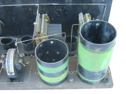
4. Columbia oscillator coupler, antenna coupler, and IF transformers.
5. Pacent rheostats and Bradley potentiometer.
6. The manufacturer of the tuning capacitors and the tube sockets is unknown.
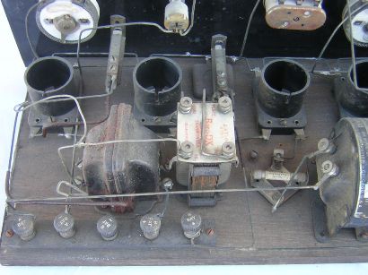
7. One audio transformer is a Boro-DX, the other one is unknown.

Close up of oscillator coupler and antenna coupler.
.
Columbia advertisement from the fall, 1924, Citizens Radio Call Book. My set had the “Multicolucord” when I purchased it.

|
Type |
Peak Freq. |
Lower 3 dB |
Upper 3 dB |
Bandwidth |
Relative gain |
Pri. ohms |
Sec. ohms |
|
#1 |
39.4 KC |
26.2 KC |
51.1 KC |
24.9 KC |
8.4 |
124.7 |
305.2 |
|
#2 |
41.7 KC |
30.4 KC |
52.5 KC |
22.1 KC |
7.8 |
124.9 |
296.1 |
|
#3 |
37.9 KC |
27.9 KC |
47.7 KC |
19.8 KC |
7.3 |
128.0 |
290.8 |
|
#4, filter |
46.3 KC |
38.8 KC |
52.6 KC |
13.8 KC |
3.4 |
117.7 |
292.6 |
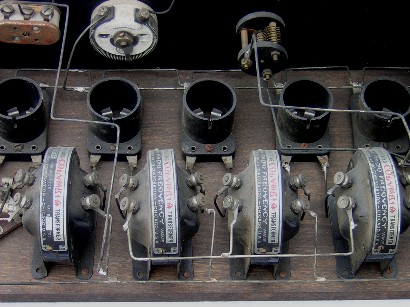
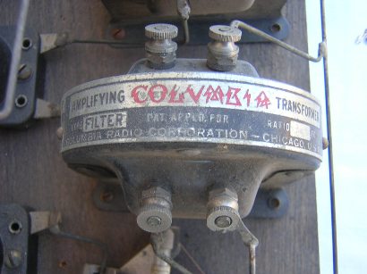
The Columbia IF transformers are constructed with brass endplates that act as electromagnetic shields. The iron-core of the first three transformers could be sensed with a magnet. The core of the fourth transformer (filter) could not be sensed with a magnet. The first three IF transformers peaked near 40 KC but the fourth transformer peaked somewhat higher at 46.3 KC. The filter transformer did not have a capacitor connected across the primary or the secondary windings, and the schematic diagram does not show one either. However, a small capacitor could probably be added to either the primary or the secondary to tune the transformer to 40 KC (Lp=57.1 mH, Ls=299 mH). The bandpass measurements are recorded in the table below.
Schematic diagram of the Ultradyne circuit. This circuit differs from the Ultradyne L-1 only in the fact that the Ultradyne L-1 includes two audio amplifier tubes. This diagram is from the 1926 Radio News Superheterodyne Book.

The Columbia IF amplifier.
The audio amplifier.


Close up of the Columbia filter transformer.
