Haynes-Griffin Square IF Transformers

The black square-shaped IF transformers marketed by Haynes-Griffin were among the first factory manufactured IF transformers available. The little square transformers date to the late 1923 time frame. In mid 1924 Haynes-Griffin changed the design of the transformer. The shape of the new transformer was round and slightly conical (as used in the Cockaday). The earlier square transformers seem to be fairly scarce.
I was lucky enough to find a complete set of four transformers, and then a separate one some time later. My luck ran out, so to speak, when I measured the resistance of the windings and discovered that the filter transformer of the set, a Type A, had an open primary winding.
Repairing this type of transformer posed quite a challenge. At first I couldn’t even see a way to open up the transformer for a simple inspection. One very cold November morning I was handling one of the transformers in my truck and the top of the transformer started to come off. The transformer had been frozen for several hours and the hard potting inside the transformer had shrunk. After a little bit of coaxing the transformer was out of the bakelite tub. The hard potting substance was something else. It’s some type of hard tar or pitch of some sort, and it has a sweet smell when broken into pieces or heated. I tried a heat gun on the stuff but it didn’t want to melt at a low temperature. The hard substance just bubbled a little bit. I tried applying a small amount of acetone to the tar with a Q-tip and the acetone seemed to soften it. I then immersed the entire transformer in a small bottle of acetone and set it outside to soak for a while. I checked on the progress after about fifteen minutes and was amazed to find out that the hard tar-like substance had completely dissolved, leaving the coils and the wires of the transformer unharmed! The tiny broken wire on the primary coil was a snap to repair after that. Talk about luck!

Haynes-Griffin Type A transformer with hard tar potting.
Schematic diagram of the Haynes-Griffin superheterodyne using the small square IF transformers. This is the standard superhet circuit of the mid 1920s (minus one audio tube). The schematic was copied from the January, 1924, Radio Broadcast magazine.
It’s kind of exciting doing a bandpass check on a set of unknown transformers because you never know what to expect. In this case the little Haynes-Griffin square transformers held quite a surprise. I was expecting a frequency peak of around 100 KC, but they actually peaked up near 230 KC! That’s a relatively high frequency for such an early transformer. For some strange reason Haynes-Griffin dropped down to 130 KC for their next generation conical transformers of mid 1924. The high frequency peak of the square transformer is not too hard to imagine considering how small the primary and secondary windings are. The wood dowel that the primary and secondary coils are wound on is only 1.125” outside diameter.
The table below shows the bandpass measurements of the transformers. The Type A filter was tested with a .000521 mfd capacitor across the primary winding. I purchased transformer #5 a year or two after I purchased the complete set of four. Transformer #5 has a slightly higher frequency peak than the other transformers, probably because it came from a different manufacturing lot. All of the transformers were measured at the same time so it wasn’t a measurement problem.
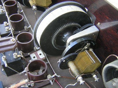
Front view of the Haynes-Griffin superhet. This set uses Tyrman drum dials for the main tuning controls. The first advertisement that I can find for the Tyrman dials was in the September 1927 Citizens Radio Call Book. The Remler variable capacitors attached to the drum dials also date to 1927; the oscillator capacitor on the left is a Remler type 649 with a patent date of 2-22-27 and the loop capacitor on the right is a Remler type 639 with a patent date of 2-22-27.
Here are a few more particulars of the set:
1. Hard rubber front panel measures 26” by 7” by 3/16”
2. Haynes-Griffin square IF transformers
3. Haynes-Griffin oscillator coupler
4. Remler “Butterfly” tuning capacitors with Tyrman drum dials
5. Thordarson R-300 audio transformer
6. General Radio rheostat
7. Carter potentiometer (with 7-10-23 patent date)
8. The brown UV type tube sockets are unknown. The audio output tube socket is a Wirco
9. Seven tubes
.

|
Type |
Peak Freq. |
Lower 3 dB |
Upper 3 dB |
Bandwidth |
Relative gain |
Pri. ohms |
Sec. ohms |
|
#1 Square IF Type A |
187.3 KC |
169.2 KC |
238.8 KC |
69.6 KC |
13.0 |
19.4 |
90.2 |
|
#2 Square IF |
226.7 KC |
195.3 KC |
254.6 KC |
59.3 KC |
10.8 |
52.6 |
87.6 |
|
#3 Square IF |
206.2 KC |
183.4 KC |
224.6 KC |
41.2 KC |
10.4 |
66.2 |
87.0 |
|
#4 Square IF |
207.1 KC |
190.4 KC |
218.6 KC |
28.2 KC |
11.2 |
63.1 |
86.2 |
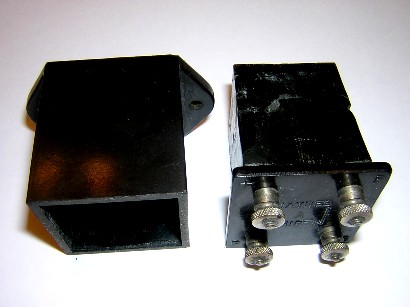
This is a close-up view of the Haynes-Griffin filter transformer first described in this section (on the left) and the Haynes-Griffin filter transformer used in the complete receiver (on the right). The IF transformers in the receiver do not show a name on them but they are obviously Haynes-Griffin. I believe the IF transformers in the receiver without the Haynes-Griffin name predate the transformers showing the Haynes-Griffin name. The plate and filament terminals on the two versions of the transformer are swapped. The second version of the transformer (with the Haynes-Griffin name) allows shorter external wires to the plate and grid terminals on the tube sockets. The square Haynes-Griffin IF transformers were only manufactured for a few months; the version without the name must be a rare bird!
The table below shows the bandpass measurements of the nameless IF transformers. The Type A filter was tested with the original Sangamo .0005 mfd capacitor across the primary winding (the capacitor measured .00052 mfd). The first three transformers were measured with A- as a secondary reference. The fourth transformer was measured with A+ as a secondary reference and the grid leak resistor and capacitor in the circuit.

Another view of the Tyrman drum dial.
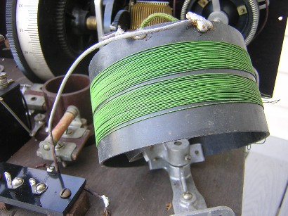
Close-up view of the oscillator coupler.


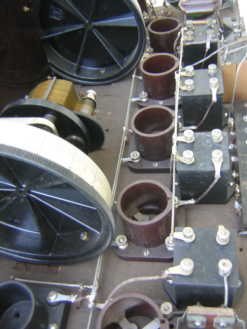
Close-up angle view of the chassis. The builder mounted the Tyrman drum dials slightly too low on the front panel and had to cut out sections of the plywood base panel to make clearance. Like I said before, this is a home-brewed set all the way. Perhaps a little more amateurish than most. But it’s got some type of charm about it that I like. I guess I’m just a sucker for old electronic things.

Rear angle view of the chassis. The base panel is some type of plywood. The terminal strips are simple affairs with soldering lugs. The UV type tube sockets were somewhat out of date by late 1927. Most of the parts seem to date from 1924 to 1927.

Top view of the chassis inside the cabinet. The tube lineup from the left to the right includes the oscillator, first detector, IF amp, IF amp, IF amp, second detector, and the audio output.


I recently obtained a complete Haynes-Griffin superhet with the square IF transformers. The set was probably made sometime in late 1927, yet the square IF transformers probably date to late 1923 or early 1924. This radio is a classic example of a home-brewed set. The cabinet is a home-brewed affair and the builder used whatever parts he could get his hands on. The circuit is wired very much like the schematic above but there are no circuit jacks; the builder used soldering lugs for the battery and speaker connections.
April 27, 2012 update:
|
Type |
Peak Freq. |
Lower 3 dB |
Upper 3 dB |
Bandwidth |
Relative gain |
Pri. ohms |
Sec. ohms |
|
#1, Square IF Filter Type A |
223 KC |
208.8 KC |
248 KC |
39.2 KC |
12.8 |
18.0 |
76.7 |
|
#2, Square IF |
229 KC |
206 KC |
247 KC |
41 KC |
8.0 |
52.0 |
69.1 |
|
#3, Square IF |
226 KC |
204 KC |
246 KC |
42 KC |
8.8 |
60.6 |
81.2 |
|
#4, Square IF |
230 KC |
208 KC |
251 KC |
43 KC |
8.2 |
55.4 |
71.3 |
|
#5, Square IF |
249 KC |
207 KC |
270 KC |
63 KC |
8.0 |
53.6 |
70.2 |


The Type A transformer after dissolving the tar with acetone.