IF Transformer Database
Several different factors control the frequency response of a 1920s IF amplifier stage. The inductance and capacitance of the secondary coil is a major factor, as is the inductance and capacitance of the primary coil. Most of the time the coils do not have an external capacitor installed across them and that makes the self-capacitance of the coils significant. The self-capacitance of the coils must be considered when making frequency calculations. Other factors that affect the frequency response include the transformer core material, the coupling coefficient between the coils, and the reactive impedances driving and loading the transformer.
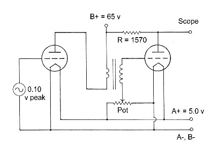
The best way to measure the frequency response of an IF transformer would probably be to measure it in the actual circuit that the transformer is used in. Unfortunately, measuring the transformer in the actual circuit is not always an easy thing to do. It’s more desirable and convenient to measure the individual transformers on the bench, but then there’s a question as to how the transformer will perform in the actual circuit. Confronted with these various problems, and having a desire to know more about my radios, I developed the test circuit of Figure 1 to help me measure the bandpass properties of an IF amplifier stage.
The first objective of the test circuit was to try and match the conditions of the actual circuit by driving the primary of the transformer with the plate of an 01-A tube and loading the secondary of the transformer with the grid of an 01-A tube.
Another objective of the test circuit was to create a circuit that would provide an easy way to measure the gain of a single transformer/tube amplifier stage. The second tube in the test circuit was therefore designed to have a gain of 1.0 so that the output voltage of the two-tube circuit would be the same as a single amplifier stage. An external resistor of 1570 ohms was calculated to produce the required gain (tube amplification factor of 8 and plate resistance of 11k ohms). The actual tube used in the test circuit required a 1850 ohm resistor. The gain of the second tube was measured to be fairly linear with frequency, dropping down by about 8% at a frequency of 500 KC.
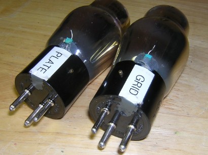
I modified two 01-A tubes so that it would be convenient to measure the transformers on the bench or in the radio (without making any wiring changes to the radio whatsoever). The grid pin of one tube was removed and the grid connection was moved up by the glass envelope, and the plate pin of the other tube was removed and the plate connection was moved up by the glass envelope. In this fashion the tubes can be inserted into the sockets of the radio and the connections to the grid and plate of the test circuit can be completed. A photo of the two modified tubes can be seen in Figure 2.
The test circuit is not a perfect way to measure the bandpass properties of an IF amplifier stage. The reactive impedances reflecting from the other transformers in the entire IF chain are not being considered. Nevertheless, the peak frequency measurements of the test circuit appears to be very accurate judging from the measurements made on transformers with known IF frequencies. There’s probably more error in the gain measurements than anything else.
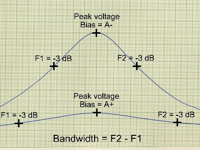
The bandwidth of an IF amplifier stage is defined as the difference in frequency between the two half-power points (a half-power point is the frequency where the voltage is .7071 times the peak voltage, or -3 dB). One half-power point is lower than the peak frequency and one half-power point is above the peak frequency. See the graph of Figure 3.
The gain of a 1920s IF amplifier stage is normally controlled by the bias voltage on the secondary winding of the transformer. This bias voltage usually comes from the wiper of a potentiometer that is connected between A- and A+. The potentiometer is identified by several different names depending on the type of radio; some common names include “Potentiometer,” “Pot,” “Volume,” and “Stability.” The gain of the IF amplifier stage decreases as the wiper is moved towards the A+ terminal, thus reducing the volume and/or stabilizing the amplifier from oscillations. As the wiper is moved towards the A+ terminal the load on the secondary winding of the transformer increases. The increasing load increases the losses and it has a net effect of reducing the output voltage of the transformer and widening the frequency response. The potentiometer is sometimes referred to as a “losser.” The upper plot in Figure 3 shows the typical response when the wiper of the potentiometer is set at the A- terminal, and the lower plot in Figure 3 shows the typical response when the wiper of the potentiometer is set at the A+ terminal.
The pot shown on the test circuit schematic is only there because that’s the way it is usually connected in a 1920s superheterodyne. I normally just connect the secondary of the transformer to A- when I’m testing a transformer on the bench and I do not include the pot in the circuit.
.
|
Transformer type |
Peak frequency KC |
Bandwidth KC |
Relative gain |
Primary ohms |
Secondary ohms |
|
ACME 30 KC |
30 |
27 |
12 |
27 |
98 |
|
All American R-120 filter |
30 |
1.7 |
9.6 |
1.4 |
20 |
|
American Radio/Standard Wave King |
145 |
28 |
12 |
30 |
39 |
|
Baldwin Pacific “Ranger” No. 20 filter |
45 |
4.5 |
17 |
39 |
149 |
|
Baldwin Pacific “Ranger” No. 25 |
45 |
66 |
19 |
87 |
290 |
|
Como 30 KC filter |
30 |
7.3 |
15 |
15 |
208 |
|
Columbia filter |
40 |
13 |
4.5 |
118 |
293 |
|
Columbia Long Wave Amplifier |
40 |
22 |
7.8 |
126 |
297 |
|
E.I.S. Model C input coupler, early |
30 |
4.7 |
15 |
26 |
26 |
|
E.I.S. Model “C” |
37 |
40 |
16 |
162 |
469 |
|
Transformer type |
Peak frequency |
Bandwidth |
Relative gain |
Pri. ohms |
Sec. ohms |
|
E.I.S. Model C-7 |
32 |
39 |
14 |
170 |
520 |
|
E.I.S. Model C-7 output coupler |
47 |
3.7 |
6.1 |
4.2 |
15.5 |
|
E.I.S. Model C-10 |
39 |
47 |
17 |
156 |
492 |
|
E.I.S. Model C-10 output coupler |
47 |
9.1 |
12 |
60 |
459 |
|
E.I.S. Model L input coupler |
30 |
6.9 |
11 |
65 |
65 |
|
General Radio 271 |
30 |
25 |
24 |
304 |
1170 |
|
Haynes-Griffin Conical |
130 |
32 |
9.2 |
81 |
140 |
|
Haynes-Griffin Conical filter |
130 |
32 |
11 |
38 |
140 |
|
Haynes-Griffin Square |
230 |
42 |
8.3 |
56 |
74 |
|
Haynes-Griffin Square Type A filter |
230 |
39 |
13 |
18 |
77 |
|
Transformer type |
Peak frequency |
Bandwidth |
Relative gain |
Pri. ohms |
Sec. ohms |
|
Jefferson 150 |
30 |
28 |
15 |
432 |
405 |
|
Lincoln “1” |
170 |
254 |
8.8 |
124 |
124 |
|
Lincoln “2” |
70 |
13 |
7.1 |
13 |
13 |
|
Lincoln “3” |
70 |
13 |
7.1 |
13 |
13 |
|
Lincoln “4” |
100 |
255 |
9.2 |
232 |
232 |
|
Madison-Moore HW-2 |
490 |
30 |
3.5 |
0.8 |
4.1 |
|
Madison-Moore HW-3 |
490 |
30 |
2.5 |
0.7 |
1.1 |
|
Madison-Moore HW-4 |
490 |
30 |
2.7 |
0.7 |
1.1 |
|
Madison-Moore HW-5 |
490 |
30 |
2.5 |
0.6 |
1.0 |
|
Master module (each section) |
60 |
17 |
12 |
68 |
137 |
|
Transformer type |
Peak frequency |
Bandwidth |
Relative gain |
Pri. ohms |
Sec. ohms |
|
Phenix Ultraformer Type A |
115 |
6.4 |
10 |
7.0 |
16 |
|
Phenix Ultraformer Type B |
115 |
6.6 |
9.5 |
7.0 |
16 |
|
Precise 1700 Multiformer (each section) |
40 |
22 |
16 |
140 |
373 |
|
Radiart Labs RF61 |
70 |
11 |
11 |
44 |
101 |
|
Radio Instrument/VirBren DX-0 filter |
80 |
4.4 |
5.7 |
254 |
104 |
|
Radio Instrument/VirBren DX-2H |
80 |
44 |
10 |
195 |
250 |
|
RCA UV-1716 |
30 |
41 |
14 |
143 |
401 |
|
Receptrad filter |
48 |
14 |
16 |
107 |
107 |
|
Receptrad RF-1716 |
48 |
29 |
16 |
94 |
280 |
|
Remler 600 |
45 |
67 |
13 |
77 |
278 |
|
Remler 610 filter |
45 |
3.3 |
7.4 |
33 |
157 |
|
Transformer type |
Peak frequency |
Bandwidth |
Relative gain |
Pri. ohms |
Sec. ohms |
|
Robertson-Davis 135 |
125 |
34 |
4,7 |
96 |
16 |
|
Robertson-Davis 461 |
410 |
22 |
3.7 |
10 |
6.2 |
|
Robertson-Davis 463 |
410 |
22 |
3.7 |
10 |
6.2 |
|
Robertson-Davis 464 |
410 |
22 |
3.7 |
10 |
6.2 |
|
Robertson-Davis 465 |
410 |
22 |
3.7 |
10 |
6.2 |
|
Robertson-Davis 466 |
410 |
22 |
3.7 |
10 |
6.2 |
|
Robertson-Davis 467 |
410 |
22 |
3.7 |
10 |
6.2 |
|
Sangamo AT-60 |
65 |
14 |
5.3 |
35 |
37 |
|
Sangamo IF-60 |
44 |
210 |
7.0 |
149 |
142 |
|
Transformer type |
Peak frequency |
Bandwidth |
Relative gain |
Pri. ohms |
Sec. ohms |
|
Samson HW-R1 |
50 |
29 |
17 |
85 |
319 |
|
Samson HW-R1 filter |
50 |
15 |
24 |
85 |
319 |
|
Scott R-400 |
35 or 49 |
40 |
8.4 |
28 |
107 |
|
Scott R-410 filter |
35 or 49 |
4.0 |
8.3 |
22 |
557 |
|
Silver-Marshal aluminum 210 |
60 |
38 |
10 |
109 |
296 |
|
Silver-Marshal aluminum 211 filter |
60 |
4.5 |
13 |
3.6 |
206 |
|
Silver-Marshal bakelite 210 |
60 |
47 |
17 |
129 |
305 |
|
Silver-Marshal bakelite 211 filter |
60 |
5.6 |
12 |
2.3 |
28 |
|
Supertone |
140 |
35 |
8.2 |
53 |
147 |
|
Supertone input filter |
140 |
32 |
6.5 |
34 |
151 |
|
Transformer type |
Peak frequency |
Bandwidth |
Relative gain |
Pri. ohms |
Sec. ohms |
|
Tropaformer |
40 to 80 |
23 |
8.2 |
17 |
34 |
|
Victoreen Input |
90 |
17 |
7.8 |
77 |
101 |
|
Victoreen RF |
90 |
14 |
7.1 |
43 |
94 |
|
|
|
|
|
|
|
The table below lists the various parameters of an IF transformer and an IF amplifier stage that should be important. Most of the data numbers are averaged out and rounded off. There’s no sense giving a value with four or five significant digits. The transformers and tubes did not have that tight of tolerances back in the 1920s, not to mention the various errors in measurement etc. If you want to see more accurate data on individual transformers then check the particular radio section for that transformer. The peak frequencies are typical values that may be encountered and they are based on the published records as well as my own measurements; they are not strictly based on my measurements alone.
Figure 3. Typical bandpass responses.
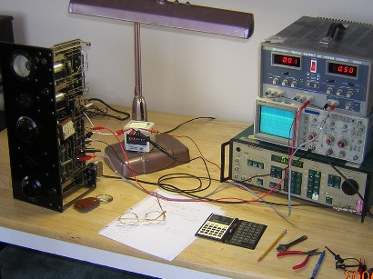
Figure 4. IF transformer measurement setup.


Figure 1. Transformer test circuit.
Figure 2. Modified 01-A tubes.

