IF Transformer Pass Band Plots (see bottom of page for method)
|
IF Transformer Pass Band Plots (see bottom of page for method) |
 |
|
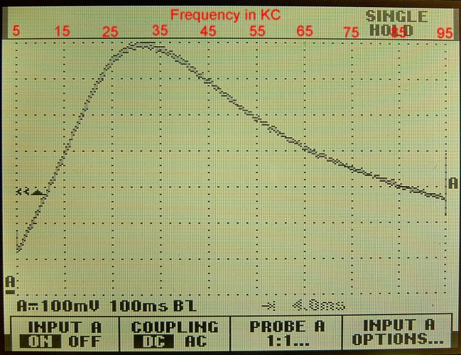
ACME 30 KC, iron core |
 |
|
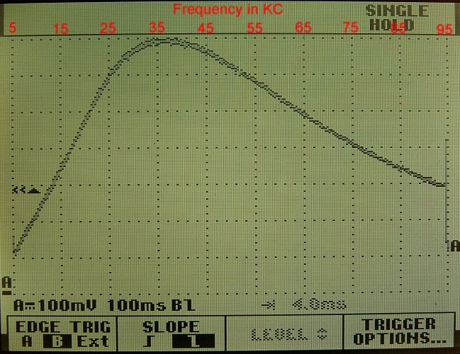
Experimenters Information Service Model C, iron core |
 |
|
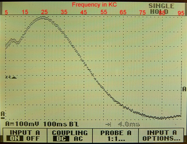
Jefferson No. 150, iron core |
 |
|
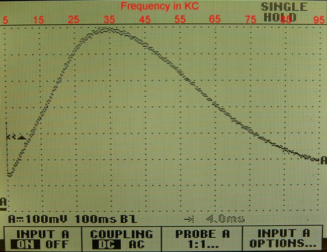
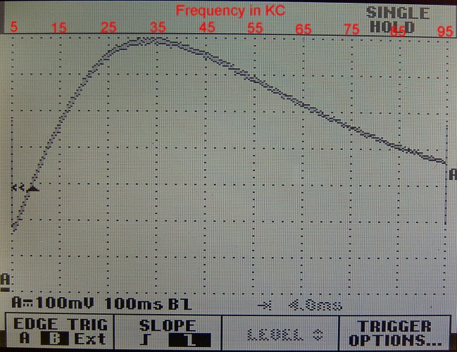
RCA UV1716, iron core |
 |
|
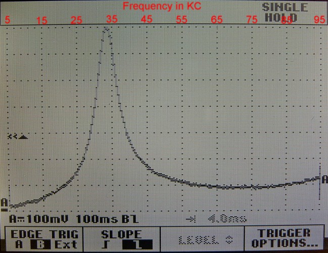
Selectone R-400, iron core |
 |
|
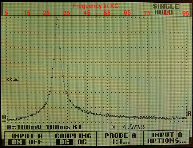
Selectone R-410, air core |
 |
|
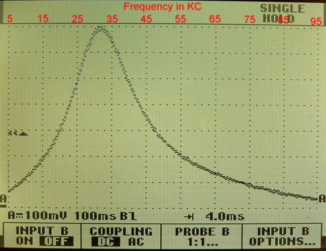
All American R-120, air core |
 |
|
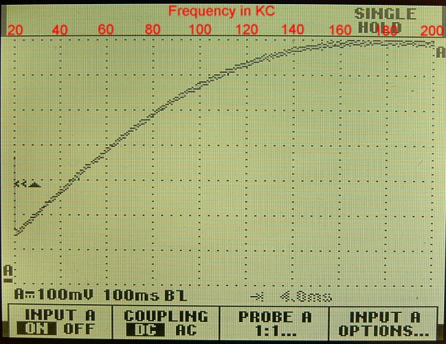
Madison-Moore Unit No. 3, air core |
 |
|
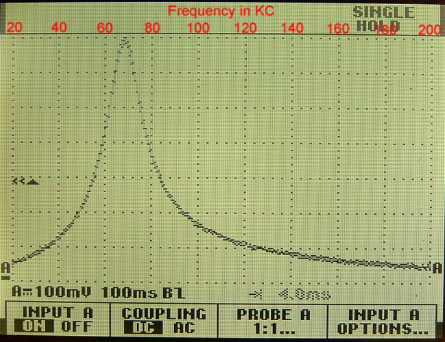
Lincoln 1, air core |
 |
|
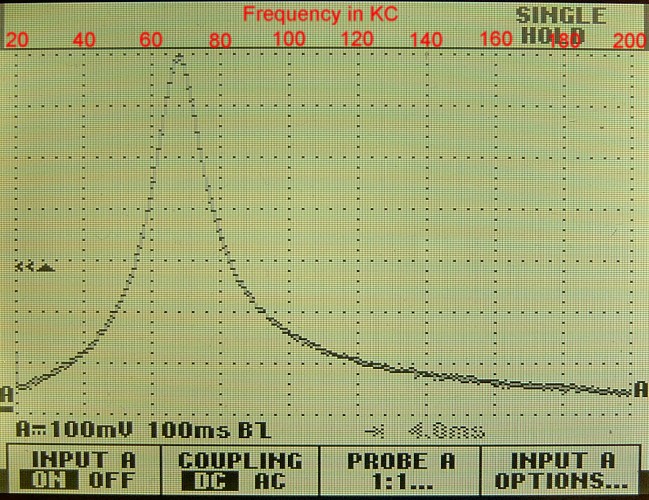
Lincoln 2, air core |
 |
|
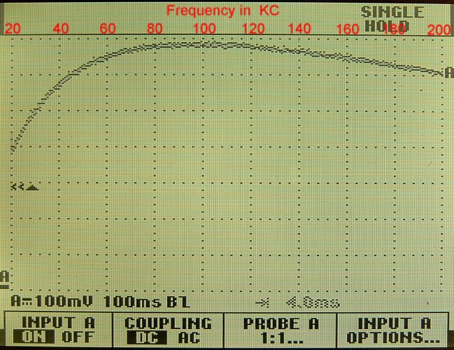
Lincoln 3, air core |
 |
|
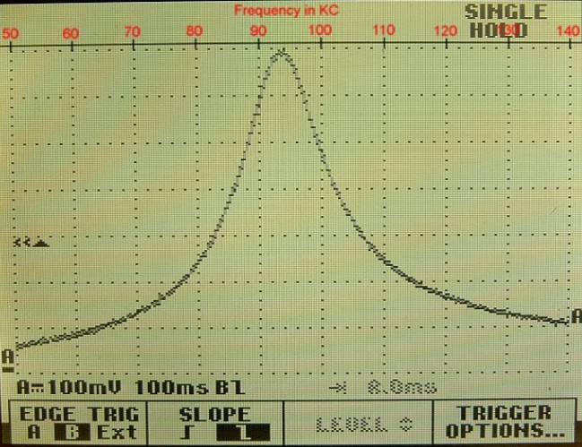
Lincoln 4, air core |
 |
|
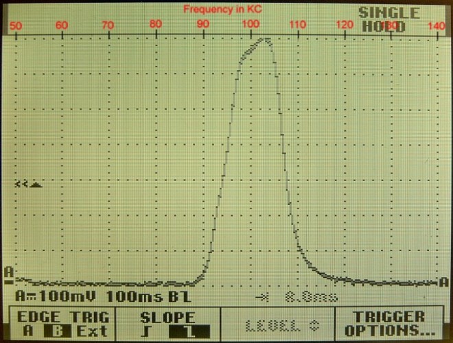
Rusco 95KC, air core |
 |
|
Rusco 10KC Band Pass Filter, air core |
|
The above pass band plots were made with the assistance of a Wavetek sweep generator (Model 166), a Fluke oscilloscope, and an operational amplifier precision rectifier, or “super diode.” See the diagram below for the setup. |
 |
|
IF Transformer Pass Band Test Circuit |
|
Notes: 1. The sweep time on the Wavetek generator was set at 900 milliseconds. |
|
An alternate method of getting a pass band on an oscilloscope instead of using a precision rectifier is to use a common diode demodulator circuit. I tried the diode demodulator circuit after I took the above photos and discovered that the response of the diode demodulator circuit was nearly identical to the response of the precision rectifier. The diode I used was equivalent to a 1N34 with a forward voltage drop of .15 volts @ .2 milliamps. The diagram for the diode demodulator circuit (as used in place of the precision rectifier) is shown below. |
|
|
||||||||||||||||||||||||||||