Infradyne/Remler

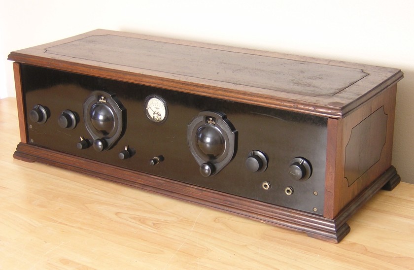
No collection of 1920s superheterodynes would be complete without at least one version of the Remler Infradyne. E. M. Sargent invented the Infradyne and the first construction article appeared in the August, 1926 Radio magazine. That first model used Thorola doughnut coils in the front end and it had a 30-inch long front panel. Numerous upgrades to the Infradyne circuit came quickly afterwards, and by October 1, 1926, E. M. Sargent’s “Official Infra+Dyne Manual” listed a total of six different improvements (but retained the Thorola doughnut coils). My example of the Infradyne uses Camfield “Duoformer” coils in the front end. The Camfield coils were first recommended in the September, 1926 Citizens Radio Call Book. The Infradyne circuit was a radical departure from the normal superheterodyne circuit of the time, or for any time for that matter!
The superheterodyne was invented during World War I out of the need to receive short wave radio signals. “Short wave” at that time was anything above about 1000 KC. The early triode vacuum tubes were inefficient at amplifying high frequencies, due mainly to the capacities between the various elements in the tube. Armstrong reasoned that if he could somehow convert the short waves, or high frequencies, into lower frequencies, then the lower frequencies could be amplified much more efficiently before audio detection. The lower the Intermediate Frequency, as the new lower frequency was called, then the more efficient the amplification would be. IF frequencies as low as 30 KC to 50 KC were very common.
The superheterodyne frequency conversion process involves mixing an incoming signal of high frequency with a local oscillator. The mixing was usually accomplished in one tube dedicated for the purpose, called the first detector. The output signal of the first detector is actually comprised of four different frequencies; the incoming signal of high frequency, the local oscillator frequency, the difference of the signal frequency and the local oscillator frequency, and the sum of the signal frequency and the local oscillator frequency. The difference frequency is the normally desired frequency because it is lower than the signal frequency. The sum frequency was always considered to be a useless byproduct of the frequency conversion process.
Enter the Infradyne. The Infradyne goes against the common logic of why the superheterodyne was invented in the first place. The Infradyne amplifies the SUM frequency of the incoming signal and the local oscillator! The IF amplifier, or “Infradyne Amplifier,” operates at about 3490 KC, and it makes a very quite superhet compared to the lower IF frequency superhets. Furthermore, there is only one spot on the oscillator dial that will bring in the incoming signal. Since the Infradyne Amplifier operates on a fixed frequency of about 3490 KC, the local oscillator frequency has to be decreased as the desired signal frequency is increased. This is just the opposite of what happens in a normal superhet. You’ve got to admire E. M. Sargent, at least for his original thinking.
Here are a few particulars of my Infradyne:
1. The radio is somewhat different from the normal superhet, amplifying the sum of the incoming signal frequency and the oscillator frequency instead of the difference.
2. The front panel measures 28” long by 7” high by 1/8” thick.
3. Remler Infradyne Amplifier, Type 700.
4. Camfield Type 22 Duoformer TRF coils and Camfield oscillator coils.
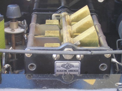
5. AMSCO .00035 mfd 3-gang main tuning capacitor.
6. Remler .00035 oscillator capacitor.
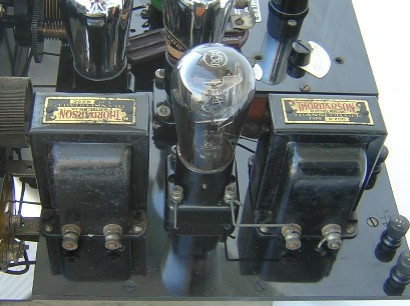
7. Thordarson R 200 audio transformers.
8. Frost rheostats and tube sockets (Benjamin shock-resistant 2nd detector tube socket).
9. Ten tubes; five UX-201, four UX-199, and one UX-171 power tube.
Underside view of the chassis.

Close up view of the Type 700 Remler Infradyne Amplifier.
Stamped on the back of the copper-shielded Infradyne Amplifier is the serial number 005700.
The above photo shows a rear angle chassis view of the fourth version of the Infradyne, using Camfield coils, as copied from the December, 1926, Citizens Radio Call Book. This Infradyne construction article was very similar to the construction article from the September, 1926, CRCB. The main difference on the base board was the swapping of the position of the oscillator tube and the oscillator coil. The main difference on the front panel was the addition of the two small vernier capacitors on each side of the 3-gang tuning capacitor. The IF frequency of the Infradyne Amplifier was updated from the old value of 3200 KC to the new value of 3490 KC, or 86 meters.

Citizens Radio Call Book, December, 1926
Infradyne version 4, Camfield coils version 2
There was an Infradyne construction article in the November, 1926, Radio magazine, but it was essentially just a reprint of the construction article in E. M. Sargent’s Official Infra+Dyne Manual of October, 1, 1926. The article did give credit to a Mr. L. C. Rayment for his part in designing the Infradyne during the previous two years. The new model was called the Sargent-Rayment Infradyne. The IF frequency specified in this printing, as well as in all future printings, was the updated 3490 KC, or 86 meters value.
Radio magazine, November, 1926
Infradyne version 3, Thorola coils version 2
This article basically describes the first version Infradyne that was described in the August, 1926, Radio magazine. There is no new information about the infradyne in this article. The article is not even a construction article because there is no parts list. (The IF frequency was specified at the outdated 3200 KC, or 95 meters value).
Radio News magazine, October, 1926
Infradyne version 1, Thorola coils version 1
The above photos show the third version of the Infradyne, using Thorola coils, as copied from E. M. Sargent’s Official Infra+Dyne manual of October 1, 1926. The front panel measures 30” long by 7” high and the base panel measures 34” long by 10” deep, just like the first version of the Infradyne. The main difference on the base board between this version and the first version is the position of the first three tubes. The front panel is quite a bit like the first version also. A person would expect that this October version with Thorola coils should be earlier than the September version with Camfield coils. Besides the later publication date, there are several reasons that this version with Thorola coils is later. One reason is that this Infradyne includes the two small vernier capacitors on each side of the 3-gang tuning capacitor, the first Infradyne to do so. Most importantly though, the IF frequency of the Infradyne Amplifier was changed from 3200 KC to 3490 KC, or 86 meters.
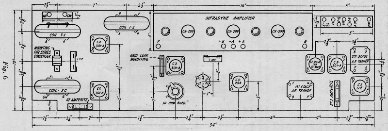

E. M. Sargent’s Official Infra+Dyne Manual, October 1, 1926
Infradyne version 3, Thorola coils version 2
The above photos show the second version of the Infradyne, using Camfield coils, as copied from the September, 1926, Citizens Radio Call Book. The front panel measured 28” long by 7” high and the base panel measured 27” long by 8.75” deep. The components were arranged in a more compact manner on the base board. The 30-ohm rheostat was moved from the baseboard to the front panel, making four small controls total on the front panel. The four small controls were rearranged to have two each on each side of the front panel. Like the first version of the infradyne, this second version had an IF frequency of 3200 KC, or 95 meters.
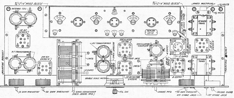

Citizens Radio Call Book, September, 1926
Infradyne version 2, Camfield coils version 1
The above photos show the very first version of the Infradyne, using Thorola coils, as copied from the August, 1926, Radio magazine. The front panel measured 30” wide by 7” high and the base panel measured 34” long by 10” deep. The front panel was 4” shorter than the base panel, making 2” wide fillers necessary on each side of the front of the cabinet. The front panel contains two large tuning dials and three small controls. One 30-ohm rheostat control is mounted on the base board. The IF frequency of this first model of the infradyne was set at 3200 KC, or 95 meters.

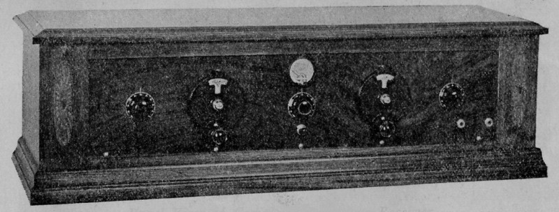
Radio Magazine, August, 1926
Infradyne version 1, Thorola coils version 1
December 30, 2013, update:
Chronology of early Infradynes
Rear view of Robert Lozier’s Infradyne. There is a mud dauber nest on the oscillator coupler. Overall it is a very clean set.

Front view of Robert Lozier’s 1926 Infradyne. It has a factory panel so it may have been constructed from a complete kit of parts.

This Infradyne does not have the two small trimmer capacitors mounted on each side of the 3-gang tuning capacitor. It is a very early Infradyne. The serial number on the Infradyne Amplifier is 005720.
Thanks Robert for the information on your Infradyne!
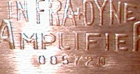
Robert Lozier sent me some great photos of his unrestored 1926 Infradyne. The base panel of this Infradyne looks like it was based on the original Infradyne article that was published in the August, 1926, Radio magazine, but the front panel looks like it was based on the second Infradyne article that was published in the September, 1926, Citizens Radio Call Book. It is unlikely that some experimenter would strike out on his own and make an Infradyne like this. There is probably a set of plans out there somewhere that describes this particular model.
November 4, 2013, update:
1928 Infradyne, serial number 6567.

S. sent me some information on a super clean 1928 Infradyne. This particular set was built without the optional Silver-Marshall Type 221 audio output transformer. The serial number on the Infradyne Amplifier is 006567. The serial number on the Remler R.F. amplifier is 371. Thanks, S., for the data on your 1928 Infradyne.
August 7, 2013, update:
The Infradyne Amplifier in Bill’s Infradyne is serial number 000952. That is a very low serial number considering that this Infradyne was probably built somewhere around mid 1927. I suspect that the Infradyne Amplifier is original to the radio. This information wipes out my old theory of nearly 6000 Infradynes being built before the 1928 model! At this moment the serial number database (a total of four serial numbers) makes little sense. What the database needs is more information! If you have a 1920s Infradyne please send me your serial number.
Thanks Bill for the information on your Infradyne!

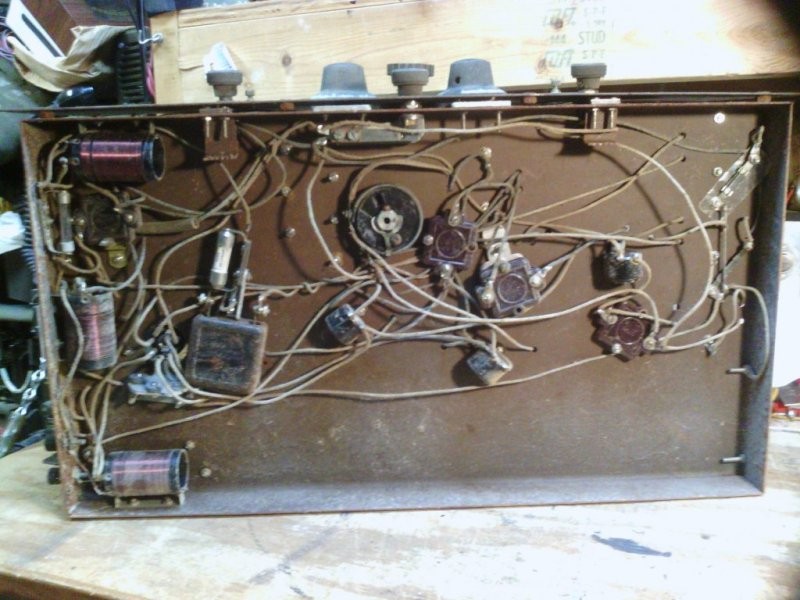


Bill KA8WTK provided the following photos of a very interesting version of the Infradyne. Some of the components are arranged like the 1928 Infradyne, and the components are enclosed in a metal cabinet. The main difference of this set from the common 1928 Infradyne is the absence of the Remler RF amplifier in the front end. Furthermore, this set uses a different 3-gang tuning capacitor and the three TRF transformers are mounted under the metal cabinet. The two main tuning capacitors and the tuning dials look more like a 1927 Infradyne than a 1928 Infradyne. The parts placement of this set is excellent and someone put a lot of thought into it.
January 9, 2013, update:
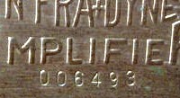
Luca’s 1928 Infradyne is s/n 006493. The serial number on Luca’s 1928 Infradyne is not too far away from the serial number on my 1927 Infradyne (s/n 005700). This is great information! It indicates that there may have been nearly 6000 Infadynes built before the 1928 models came out. Luca’s 1927 Infradyne, s/n 000441, indicates that there may be less than 400 1926 Infadynes built. It is great information, but it would mean a lot more if we could add to this very small database.
The 1927 and 1928 Infradynes owned by Luca Posca, of Italy.
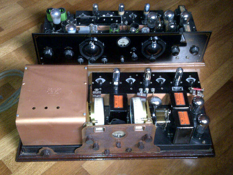

The above Infradyne (s/n 000441) is presently owned by Luca Posca, of Italy. Luca has an impressive collection of 1920s superheterodynes and sent me the photos below of his 1927 and 1928 Infradynes. The 1928 Infradyne had an “extreme makeover” from the 1927 version, as far as inside and outside looks go, but the electronic circuitry remained essentially the same. The first thing to be noticed on the 1928 Infradyne is the bulky cabinet made out of solid sheet copper. This 1928 Infradyne has Infradyne Amplifier serial number 006493. Thanks for the information and the photos, Luca!
September 21, 2012, update:


An anonymous person sent in the photos below of an Infradyne that was apparently on eBay several years ago. This Infradyne looks like it was patterned after the December, 1926, Citizens Radio Call Book. The chassis is nearly identical to my Infradyne, but notice that the oscillator tube and the oscillator coil are swapped. The serial number on the Infradyne Amplifier is 000441. Thanks for the photos John! Please keep them coming guys!
February 20, 2012, Update:

I would like to start some type of Infradyne Registry for the purpose of learning more about these very interesting radios. One of the goals of a registry like this would be to identify the different versions and be able to pinpoint more accurately the date that they were made. So, please send your Infradyne photos, along with the serial number information on the Remler Infradyne Amplifier, and I will post them here. Thank you for your support!
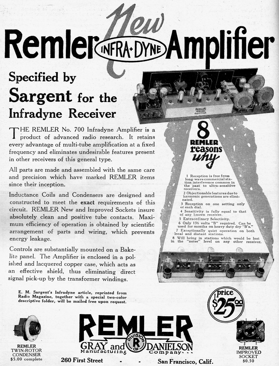
Remler advertisement for the Type 700 Infradyne Amplifier, as copied from the September, 1926, Citizens Radio Call Book. The Infradyne pictured in the upper right is the very first version Infradyne with Thorola doughnut coils (August, 1926). In Sargent’s Official Infradyne Manual of October 1, 1926, the Thorola doughnut coils were still used but the placement of some of the tubes were different (there was only two tubes near the Thorola doughnut coils instead of the three in a line as seen here).
Another front view of my Infradyne, this time with the lid closed.

Schematic diagram of the improved Infradyne, as copied from the December, 1926, Citizens Radio Call Book. One difference between this schematic and my set is that my set has a trimming capacitor across each gang of the 3-gang main tuning capacitor; this schematic only shows a trimmer on the first two gangs of the capacitor. There could be other slight differences. The Infradyne was continually being upgraded and probably the only way to get a correct schematic of my set will be to trace out the wiring.

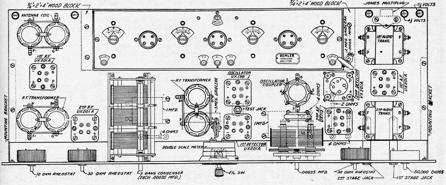
This is the base panel layout of my Infradyne, as copied from the September, 1926, Citizens Radio Call Book. This layout is nearly identical to the layout of my set. The main difference is that my set has small vernier trimming capacitors on each gang of the main 3-gang tuning capacitor, two of which are located on the front panel just under the main tuning control. E. M. Sargent included the small trimmer capacitors in his official Infradyne manual of October 1, 1926. Only the earliest Infradynes do not have the small trimmers. Another difference is the test jack located between the oscillator tube and 1st detector tube. My set has a hole in the base panel for the test jack but the jack was never installed or wired.
A construction article for an improved Infradyne came out in the December, 1926, Citizens Radio Call Book. The layout was nearly identical to the September layout, but it included the small trimming capacitors on the 3-gang main tuning capacitor. The locations of the oscillator tube and the oscillator coupler were also swapped. The reason for swapping the oscillator tube and coupler was to shorten the length of the wire going from the oscillator coupler to the Infradyne Amplifier.
My set has some of the features of the September, 1926, Infradyne and some of the features of the December, 1926, Infradyne. Judging from the serial number of the Infradyne Amplifier, S/N 005700, I would estimate that my set was built sometime in 1927, possibly towards the summer of that year.
Close up view of AMSCO 3-gang main tuning capacitor.
Close up view of the audio amplifier.
Close up view of Camfield Duoformer coils.
Close up view of Camfield oscillator coils.

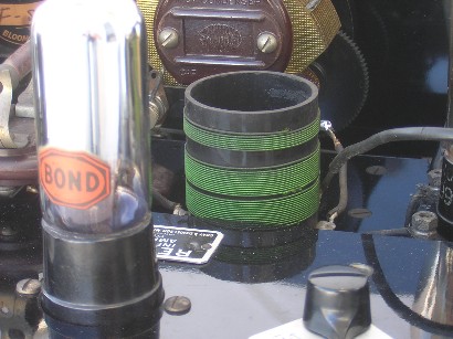


Rear angle view of the chassis.

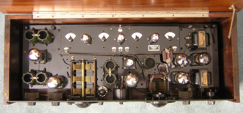
Top view of the chassis inside the cabinet. The original cabinet for this radio was apparently not deep enough for the chassis (slightly over 10 inches) and the owner had to bust off the ends of the cabinet from the grooves forward so that the chassis would fit in the cabinet. A good friend of mine, Dave Kyte, is a woodworker and he was able to make new ends for the cabinet and extend the grooves forward by about 1/4 inch.
The Infradyne Manual, 1927 edition, Revised and Corrected June 1, 1927
Infradyne version 5, Camfield coils version 3
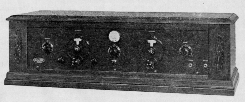
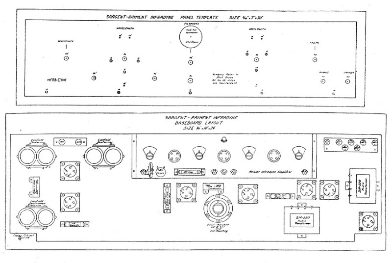
The two photos above show a fifth version of the Infradyne, using Camfield coils, as copied from the updated edition of the Infra+Dyne manual of June 1, 1927. The front panel looks the same as the Infradyne from the Official Infra+Dyne manual of October 1, 1926. The main difference here is the use of Camfield coils instead of Thorola coils. This design specifies a Silver-Marshall oscillator coupler and two Silver-Marshall audio transformers. Note that the 30 ohm rheostat has been removed from the center of the baseboard, among other minor changes. The front panel is 30” long by 7” high and the baseboard is 34” long by 8” deep. The IF frequency was still listed as 3490 KC, or 86 meters.
This manual states that the Remler Type 710 RF amplifier, as used in the front end of the “1928” Infradyne, will be ready on August 1, 1927
February 13, 2014, update:
Jim W. sent me the photos below of a very nice Infradyne that has been in his family since the 1920s. As a matter of fact, Jim’s “Uncle Clyde” was the very man who made the set from a kit (at least that’s the way the story has been passed down through the years). I believe the set to be professionally manufactured. The bus bar wiring between the different components is precise and this type of wiring job was usually done by someone very experienced at wiring radios. Congrats to Uncle Clyde if he was indeed the man who built it!
Jim’s set was most likely built following plans published in the Infra+Dyne manual of June 1, 1927. Slight differences include the three audio transformers (Silver-Marshall) instead of two, and the Jones plug for connecting batteries instead of binding posts. I would guess that this set was made in mid to late 1927. I think the set is a wonderful example of a somewhat early Infradyne. I don’t know what the serial number on the Infradyne Amplifier is but I will update this info if/when I find out.
Thanks, Jim, for the information on your great Infradyne!
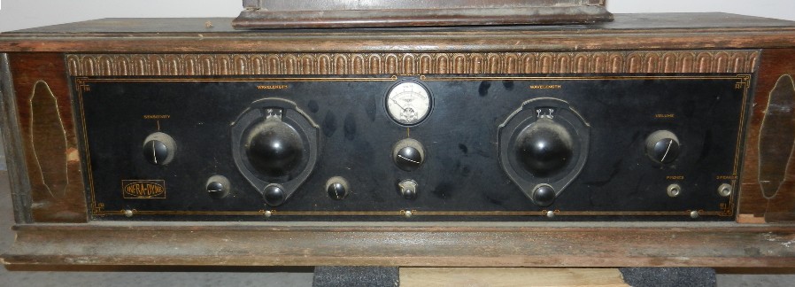
Front view of Jim’s Infradyne. It’s got a factory panel that was designed to go with the construction article in E. M. Sargent’s Infra+Dyne manual of June 1, 1927. The set was probably constructed from a complete kit of parts.

Inside chassis view of Jim’s Infradyne. The individual components are laid out real nice on a wood base panel with all the expert wiring plainly visible - you gotta love it!
December 13, 2014, update:

The above 1928 Infradyne was listed on eBay in October, 2014. It has an Infradyne Amplifier with serial number 001553, and it has an RF Amplifier with serial number 000271.
May 17, 2015, update:
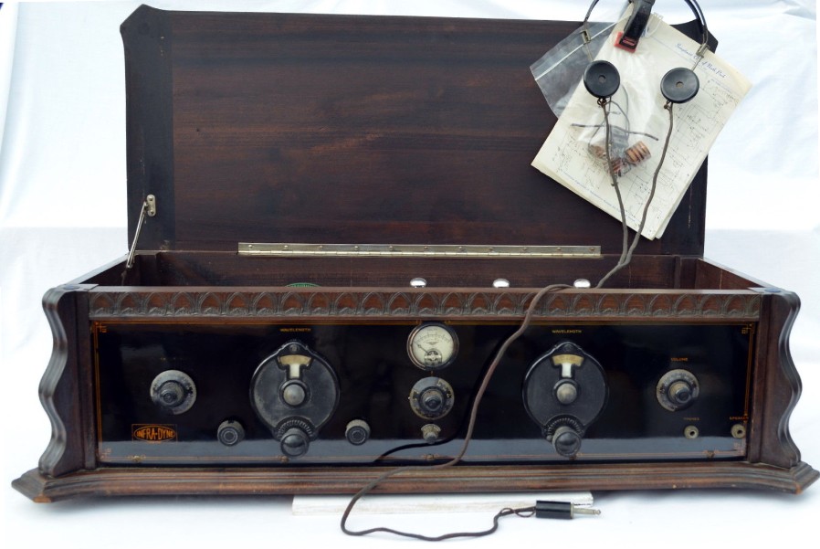
This wicked looking Infradyne was listed on eBay in May, 2015. It is based on the construction article in E. M. Sargent’s Official Infra+Dyne manual of October 1, 1926. The serial number on the Infradyne Amplifier is 000456.

Inside view of Infradyne serial number 000456. The factory panel is 30” long but the cabinet is a few inches shorter than recommended. The inside baseboard is therefore a few inches shorter than recommended, resulting in some crowding of components (mostly recognized in the right side audio section). This Infradyne is one of the best that I’ve seen.
It is interesting to note that this Infradyne was located in San Diego, California. Luca Posca’s 1927 Infradyne, serial number 000441, was also located in southern California (when in was auctioned on eBay).
May 20. 2015, update:

Here is another Infradyne that was recently offered on eBay. You might find an Infradyne on eBay once every two or three years. It is very unusual to see two of them listed within just a few days of each other! This one is based on the construction article in E. M. Sargent’s Official Infra+Dyne manual of October 1, 1926, and it follows the construction plans very accurately.
This one also came from southern California (Gardena). Unlike the other two I know of from southern California, with low serial numbers in the 400’s, this one is serial number 005838. Just when you think there may be a pattern emerging from looking at the serial numbers (and possibly the geographic locations), something like this comes along and blows all the theories away!
05-31-2015 update: Steve M., the new owner of the above Infradyne, e-mailed me some additional information about the set: “This radio turned out to be in great shape. The tubes are all marked with 1927 engraved by the owner on the bases-and they are all good. The radio may have been factory assembled. All bussbar wiring is professionally installed. Each joint is insulated. The wire seems to be painted with a translucent green coating. The spring-suspension tube sockets are all like new. The coils have good color and the labels are perfect.”
The construction plans for this particular Infradyne date back to October 1, 1926, but the 1927 engraved dates on the tubes indicate that the radio was actually constructed sometime in 1927.
Thanks for the great information, Steve, and congratulations on getting this great Infradyne!
August 21, 2018 update:

Photo of the logo data of Infradyne Amplifier serial number 191. This amplifier has the lowest serial number that I’ve seen, and the style of the digits is different than all others (no leading zeros before the actual number). In addition, the serial number is stamped on only one side of the amplifier (all other serial numbers that I’ve seen are stamped on both sides of the amplifier). The amplifier showed up on eBay in August, 2018.
In the early development stages of the infradyne an intermediate frequency of 2000 KC was tried. The tuner frequency and the oscillator frequency crossed each other at exactly 1000 KC, and it produced a 120 KC wide dead spot in the receivers reception centered around 1000 KC. Being adjusted to nearly the same frequency, the oscillator was feeding so much energy into the antenna so that “the radio frequency tubes were partially paralyzed”.
From the above experiment Sargent and Rayment immediately deduced that the frequency of the Infradyne Amplifier had to be at least twice what the highest frequency of the tuner was. With a desired upper frequency of 1500 KC, the Infradyne Amplifier must operate at well over 3000 KC. Other factors had to be considered, such as the problems of designing a high frequency amplifier and the tuning range of the oscillator. After many trials and errors a frequency of 3200 KC was decided on for the original August, 1926 Radio article. That frequency did not last very long at all, because in the very next issue of Radio Sargent was saying that the new frequency was 3490 KC!
Well, Infradyne Amplifier serial number 191 was the earliest one I have seen, and I thought there was a chance that it operated at the original frequency of 3200 KC. I purchased 191 to test my theory, but I was a little disappointed when I found out that it operates at 3490 KC. The frequency response of serial number 191 was nearly identical to the frequency response of serial numbers 000456 and 005700. The secondary windings of the transformers would probably control the resonant frequency more than anything else, and the secondary windings in all three amplifiers had 35 turns. I am on a quest now to locate an Infradyne Amplifier that works at 3200 KC. Going one step farther, an ultimate goal is to determine the actual transition point where the amplifier changed from 3200 KC to 3490 KC, if such a point even exists.
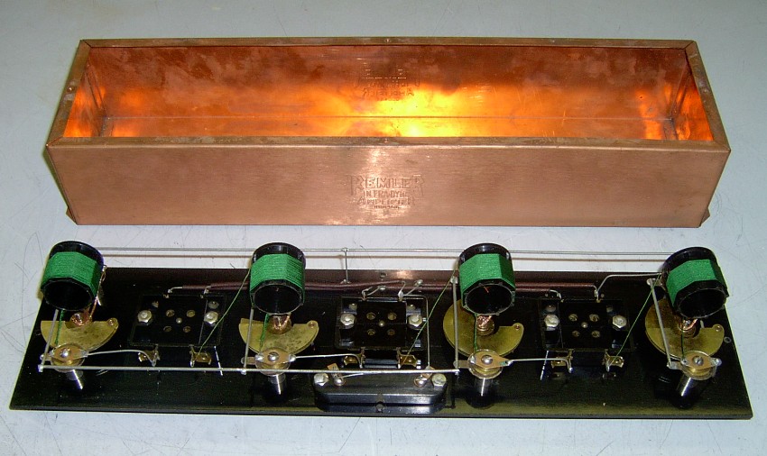
Inside view of Infradyne Amplifier serial number 000456. These are well designed amplifiers with good quality components. The first three transformers in these amplifiers have 35 turns on the secondary, but the fourth transformer has 28 turns. I believe this was for impedance matching with the second detector. When tuning these amplifiers you may notice that the fourth tuning knob has to be adjusted a little more clockwise than the other knobs.
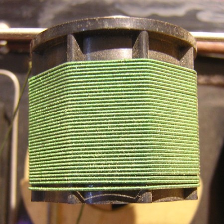
Close up view of one of the transformers in Infradyne Amplifier serial number 191. The secondary coil has 35 turns and with the associated capacitors it is resonant at 3490 KC. It looks like the coil form was originally designed to hold a coil with more turns. A 3200 KC resonant transformer will probably have several more turns on the secondary.
November 29, 2019 update:
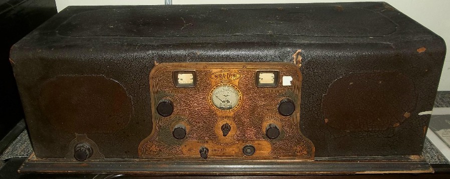
Don Patterson sent me these photos of his 1928 Infradyne. This radio is in excellent condition considering the fact that it has not been restored. If it were mine I would leave it just the way it is. Don obtained this radio many years ago from his good friend John H. Caperton.

Top chassis view of Don Patterson/s 1928 Infradyne.

This is an interesting view showing the underside of the chassis. Don, thank you for sending me these photos!
February 1, 2020 Update:

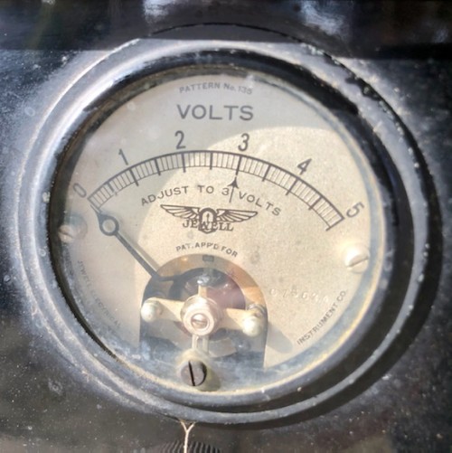
This is an Infradyne that showed up on eBay in January, 2020. One of the first things that I noticed was the lack of two small vernier tuning controls at the bottom of the left main tuning dial. This is a good sign that the Infradyne is a very early one. The receiver was probably built by following the plans published in the September, 1926, Citizens Radio Call Book. The small knob located below the meter was a design change (from the published plans) by the builder of the radio.
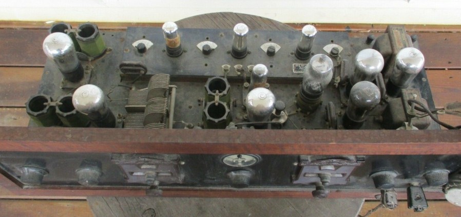
Top chassis view of the Infradyne. This view shows that most of the radio was built very close to the published plans, except that this radio is a very rare version of the Infradyne with eleven tubes! Ha ha! The eleventh tube is actually a bogus tube that is sitting inside the oscillator coupling coil. The base panel has a hole between the oscillator tube and the first detector tube that was meant for a test jack, but the jack itself is not there (similar to my set at the top of the page).
I contacted the seller, Brian, and he informed me that the serial number on the Infradyne Amplifier is 004121. Thank you, Brian, for this great information, and for giving me permission to use your photos!
December 11, 2020 update:
Not all 1920s superheterodynes are in the hands of radio collectors. Some of these old sets from a bygone era are still being found out in the wild to this very day. Take this infradyne for example that was found by Peter Fraser just a couple of weeks ago in a mountainous area near Oakland, California. It is an excellent example of an infradyne that appears to have never been touched. It’s like a time capsule that has been sitting around for some 95 years for someone to come along and discover it. Thank you, Peter, for letting me use your photos on my website!
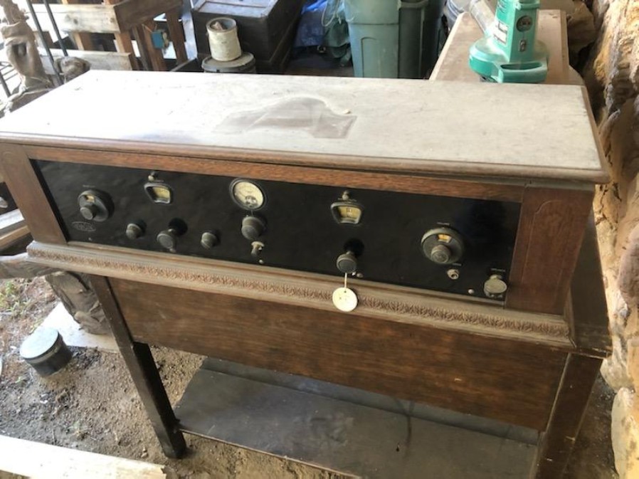
As found, with years of dust on top of it. This set was professionally made from a kit with a factory engraved panel.

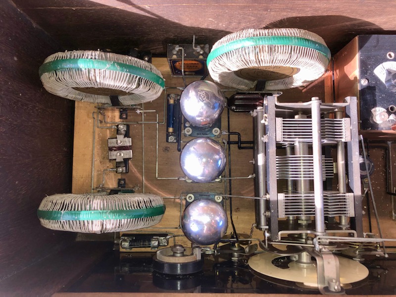
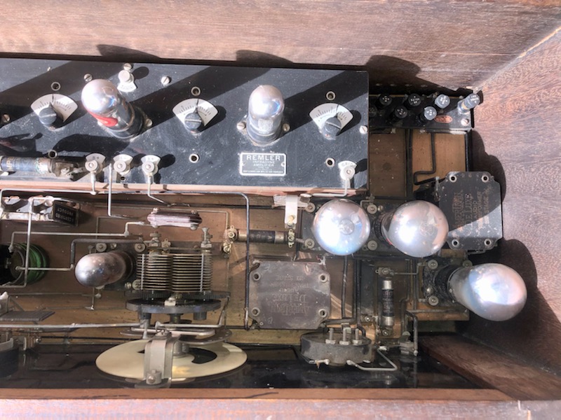
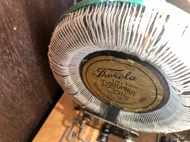
Interior view of the chassis. The Thorola doughnut coils and the tube layout indicate that the set was constructed by following plans from the August, 1926 Radio magazine. However, it’s got vernier capacitors on each side of the 3-gang tuning capacitor, which means the set was made a few months later, or it was later modified with the verniers.






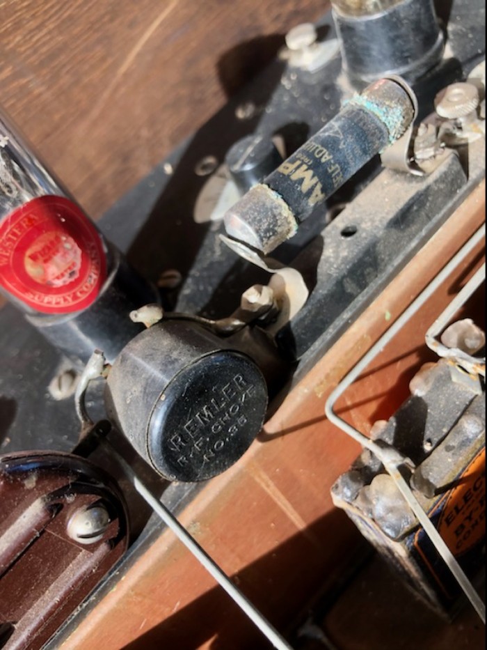

Infradyne amplifier serial number 001087
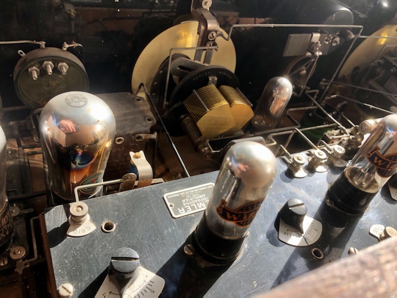


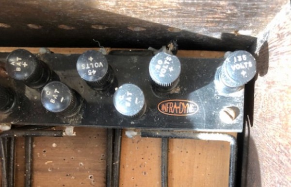
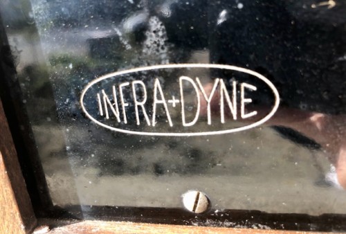
The Infra+Dyne logo is located on the battery terminal strip as well as the front panel.
This is one of the best infradynes I have ever seen. Most of the photos speak for themselves.
Once again I am grateful to Peter for sharing these photos with me and allowing me to use them.
October 1, 2023 Update:
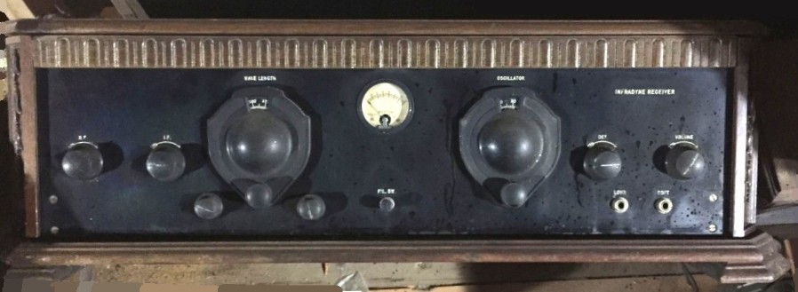
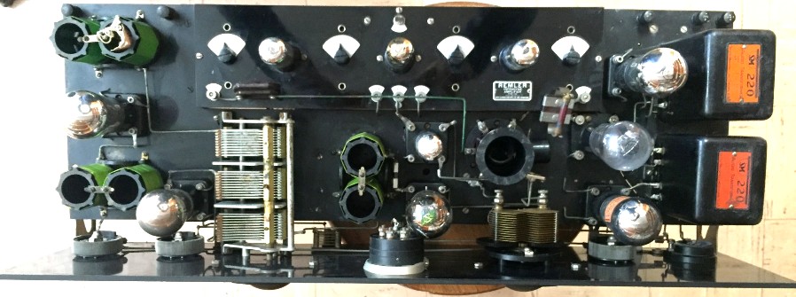
Michael Thompson found this infradyne in the attic of the New England Wireless and Steam Museum a couple of months ago. This infradyne is nearly identical to my infradyne (serial number 005700), except this one is better than mine because it has a nicer cabinet and the front panel is engraved. This infradyne uses a front panel and a base panel that was based on the September 1926 Citizen’s Radio Call Book construction article. The front panel is easy to identify. The base panel is a little more difficult to identify. Most of the parts follow the layout in the magazine. The main identifier could be the small hole in the baseboard between the oscillator tube and the third RF amplifier tube (1st detector). This hole was supposed to be for a test jack, which the builder did not install. The location of the three tubes in the audio section differ somewhat from the construction article, most likely because of the huge Silver-Marshall type 220 audio transformers. This set has the two small vernier capacitors on each side of the left side large tuning dial. This was an upgrade from the September article that the builder could have originally installed or added later.
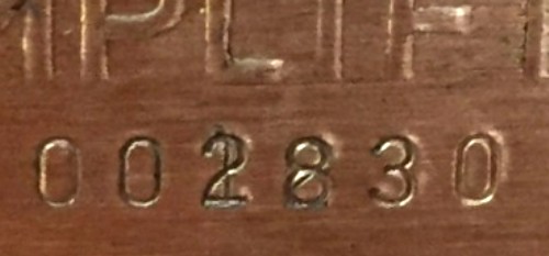
Serial number of the New England Wireless and Steam Museum infradyne. It looks like it was originally stamped 001230, then re-stamped with the number 002830! A very interesting situation. Who knows what the reason was?
Thank you Michael for the photos and the information, and for giving me permission to use them!
February 6, 2024 Update:
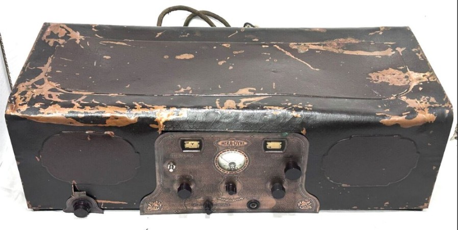
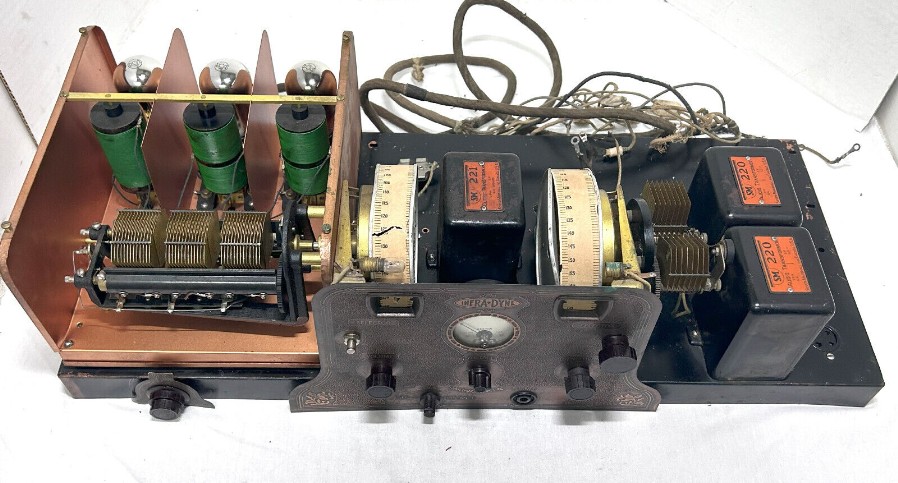
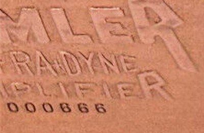
This infradyne showed up on eBay in December, 2023. It is clearly a 1928 version, yet the serial number on the infradyne amplifier is only 000666! It kind of gives final evidence that the serial number on the amplifier means little towards the date that the radio was made.
Curt Reed, a popular member of the Antique Radio Forum, once owned this radio. Here’s what he said in a post on August 11, 2006:
“One of these days I will dig it out of storage and try to get some pictures of it. But the cover was all smashed down over forty years ago when I first saw it. I think there must have been a bottom plate, as a few parts are exposed under the chassis and if so, I am lacking the bottom plate. In fact, I don't even know if it has the three 201A's in the shielded compartment. All the other tubes, like the 99's are missing and the two 201A's on the right hand side of the set. Like I said, this set, I have known about for 43 years now and I only took possession of it three years ago when I picked it up and put it in one of my storage units. The more I think about it, the more I become interested in it. Curt”
Curt passed away in 2010.
.