E.I.S./Leutz Model C/C-7 Hybrid

This set originally started out as a Leutz Model C superheterodyne (probably 1923) but was later upgraded with a number of Leutz Model C-7 components (probably 1924-1925). The people that built their own superheterodynes in the mid 1920s wanted the best radios that they could get their hands on. The radio technology was rapidly changing though, and after only a few short months there was always something better that came along. This Model C/C-7 hybrid is the results of an owner trying to keep current on state-of-the-art technology.
One of the advancements of the Model C-7 over the Model C was the introduction of a regenerative first detector (the regeneration was controlled by a small variable capacitor on the front panel). The regenerative first detector of the Model C-7 made the set so much more efficient than the Model C that one stage of IF amplification could be eliminated. The Model C had eight tubes but the Model C-7 only needed seven.
Except for the changing of the main 4-inch tuning knobs, this Model C/C-7 hybrid set looks very much like an early Model C (thanks to the engraved E.I.S. Model C front panel). The main difference is with the internal components. The lid is missing from the cabinet and the set needs a little bit of restoration work. I plan on replacing the lid but I will probably keep the internal components about the same way as they are now. Here are a few particulars of this set:
1. The engraved E.I.S. Model C front panel measures 40 inches long by 8 inches high by 1/4 inch thick.
2. E.I.S. Model C-7 antenna coupler and oscillator coupler (plug-in style).
3. Four RCA UV-1716 IF transformers.
4. General Radio tube sockets, rheostats, and audio frequency transformers.
5. Karas Orthometric tuning capacitors.
6. Weston Model 301 panel meters.
7. Eight tubes.
.
Close-up view of the plug-in C-7 antenna and oscillator couplers. The C-7 couplers were available with screw terminals (non interchangeable) or with plug-in terminals (interchangeable, as shown here). The C-7 coils as shown here are much higher quality than the coils that are used on my C-10 superhet.

|
Type |
Peak Freq. |
Lower 3 dB |
Upper 3 dB |
Bandwidth |
Relative gain |
Pri. ohms |
Sec. ohms |
|
UV-1716 |
31.7 KC |
16.0 KC |
63.1 KC |
47.1 KC |
21 |
171.6 |
399 |
|
UV-1716 |
35.2 KC |
19.8 KC |
67.1 KC |
47.3 KC |
21 |
138.9 |
356 |
|
UV-1716 |
32.5 KC |
18.2 KC |
61.1 KC |
42,9 KC |
21 |
139.4 |
405 |
|
UV-1716 |
38.3 KC |
24.4 KC |
56.5 KC |
32.1 KC |
25 |
131.7 |
396 |
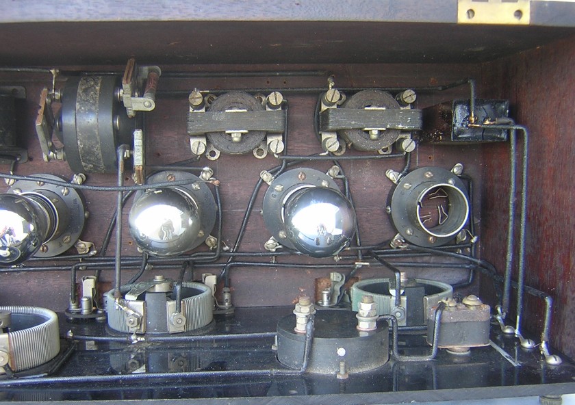
Top inside view of the audio amplifier. The previous owner removed the customary 400-ohm potentiometer for controlling amplification in the IF amplifier and installed a filament rheostat in its place. Two wires for controlling the IF amplifier bias passed through the rear panel behind the first audio transformer. The owner had some unknown external method (perhaps a simple battery) for controlling the IF amplifier bias.
The table below shows the measured frequency response of the IF amplifier stages. The first three transformers were measured with A- for a secondary reference. Transformer number four was measured with its secondary referenced to A+ and the grid leak resistor and capacitor in place.

Top internal view of the IF amplifier. The builder removed the original Leutz Model C RF coupler (input filter transformer) and substituted an RCA UV-1716 transformer. The UV-1716 IF transformers indicate that this was an early Model C. The transformers are turned 90 degrees from each other to help eliminate electromagnetic coupling between each stage. The owner of this radio definitely knew something about what he was doing. Each transformer is also shunted with a .00015 mfd capacitor on the primary winding, perhaps in an attempt to peak the frequency response. I did a bandpass measurement on each IF stage and could not see much of a difference from the standard UV-1716 transformer without the capacitor. When I purchased this receiver it had good original brass-base tipped rainbow tubes in the above socket locations. I have stored the original tubes in a separate box. This set has not be tampered with since the mid 1920s (though I do believe the missing lid was something more recent because there is very little dust inside the set).

Top internal view of the RF front end with the antenna coupler (small) and oscillator coupler (large) installed.

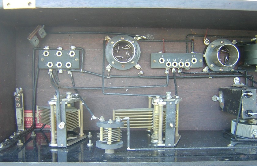
Top internal view of the RF front end. The antenna coupler and the oscillator coupler are removed from their sockets. The plug-in type C-7 coils allowed the user to change frequency bands easily; something that the original Model C could not do. Both of the coils are engraved with the letter A, for the main broadcast band. The small variable capacitor for controlling regenerative amplification in the first detector is located between the two large tuning capacitors.
