E.I.S./Leutz Navy Model C-10
The receiver has a small door in the rear to allow access to the five interchangeable coils. This is set “A” for the broadcast band. These coils are a higher quality than the coils in my other C-10 receiver. In fact, everything in this receiver is of higher quality than my other C-10 receiver.

Close-up view of the front panel.

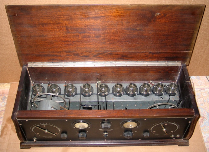
Top inside view of the set. The main tuning capacitors are gear-driven. This set was professionally manufactured.

Front angle view of the set with the lid open. The set has high-quality General Radio tube sockets. No expense was spared in making this set. At an original price of $250, it was about the best that you could buy in 1925.
The set is completely original, including a Leutz factory engraved front panel. The set could use a little TLC but at this time I have no plans to do any restoration work.

April 6, 2013 update
A Norden-Hauck version of the Navy Model C-10 Super-Heterodyne.
One final view of the receiver. The cabinet was simply cleaned with soap and water and given a rubdown with Howard’s Feed-N-Wax wood preserver.
The bottom right front base panel seen in this photo had to be repaired. I put the base panel on a belt sander and made a nice clean cut out of the jagged break. I then obtained a piece of walnut and rough shaped it into the desired form. Keeping the grain the same, I glued the small piece to the corner of the base panel and then made final sanding into the correct shape. With a little bit of stain and finish it is very difficult to see the repair. There are other cabinet imperfections that are worse than the right front corner now. I didn’t want this set to look brand new anyway. I wanted it to look like an old original set.
I do not consider this set a real good performer. The main problem is probably that there is no trimming adjustment for the first three TRF tuning stages. It seems to work OK in the TRF mode, but when it is switched to the superhet mode there are many spots on the oscillator dial where the station comes in. I looked at the oscillator signal with an oscilloscope and saw a lot of harmonic distortion and high frequency oscillations. A different oscillator tube could improve the results I suppose. I personally think that there is something wrong with the way that the oscillator coils and the pick-up coil are wired. I rewired the set the way it was originally wired though. An additional bypass capacitor would probably eliminate some of the oscillations. However, I wanted to keep the set as original as possible.
This receiver was finished in May 2010. I didn’t record how many hours that I worked on it but I imagine that it was several hundred hours. Making the multifunction switch for the meter probably took ten to fifteen hours alone (it took two or three different versions to get an acceptable switch).
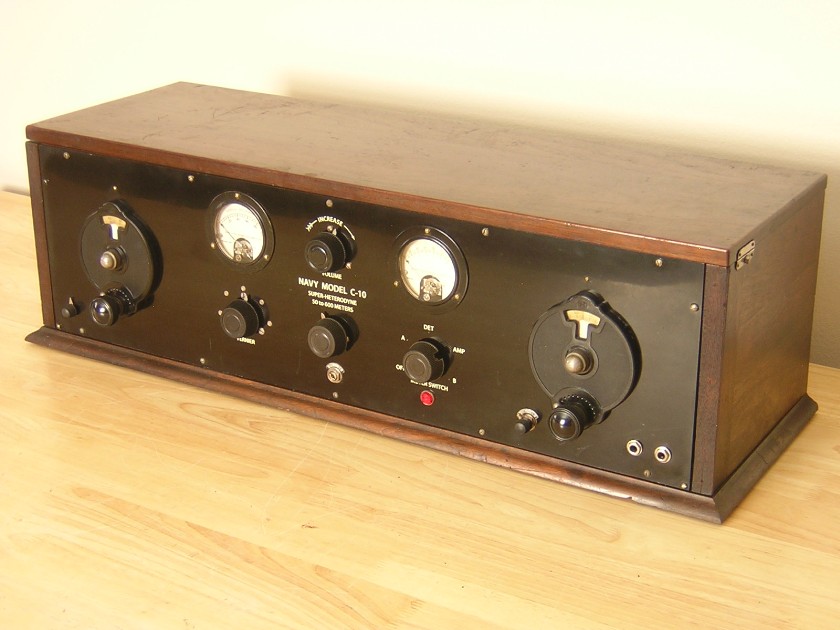
Front view of the completed receiver. There were small holes above the original Bremer Tully tuning dials which made me think that there was some other dial intended for this set. The mysterious holes were a perfect fit for the National Type B vernier dials that I installed on the set. The National dials look much nicer than the Bremer Tully dials.
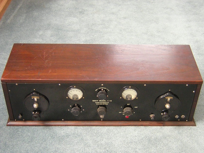
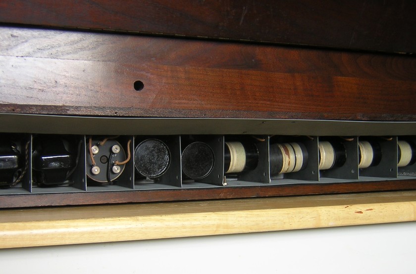
Photo showing the access area for the transformers. The shielded door hinges up for transformer replacement.
Top view of the completed radio.
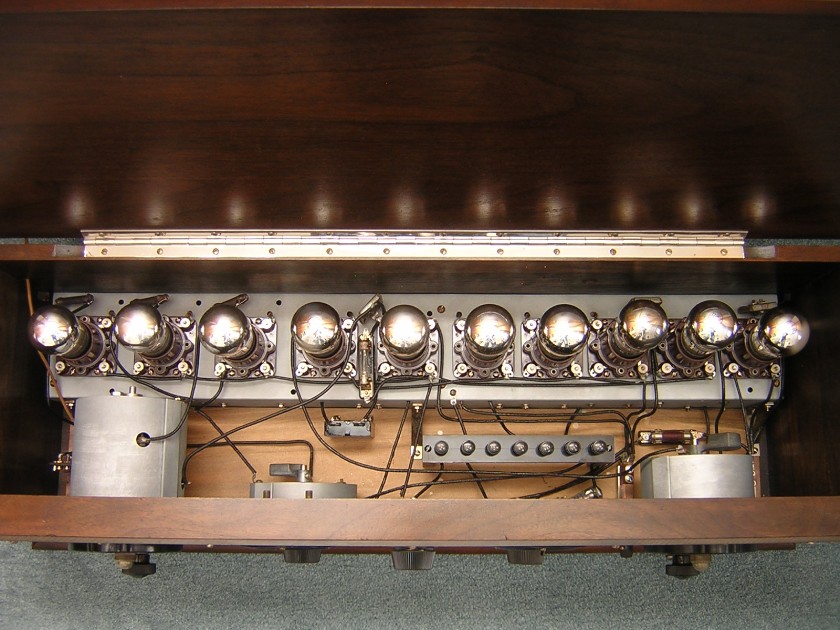
Photo showing the completed chassis with tubes installed in the cabinet. This is one beautiful radio!
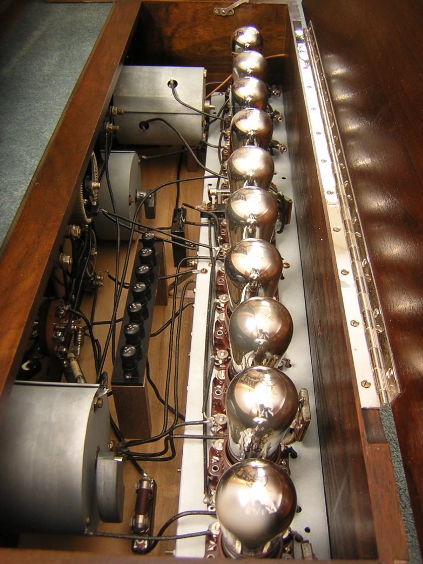
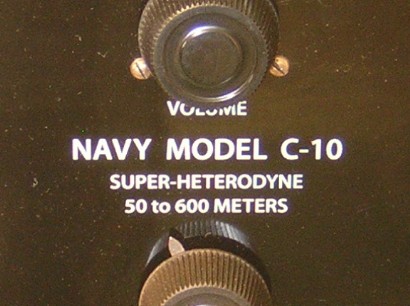
Photo showing the new silk screened lettering. I tried to match the original lettering as closely as possible.
Photo showing the original front panel lettering.

Another view of the completed chassis.

This photo shows the completed chassis wiring. 95% to 98% of the original wiring was used in the reassembly of the radio. I put black shoe lacing over the few new wires and dipped them in shellac. It’s nearly impossible to tell the original wiring from the replacement wiring.
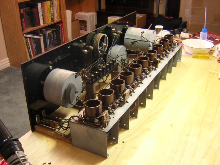
Another photo showing the rebuilding of the transformer shielding assembly. A diluted solution of hydrofluoric acid was lightly smeared on the fresh solder joints with a Q-tip to take off the shine. The new solder joints look like they are eighty years old.
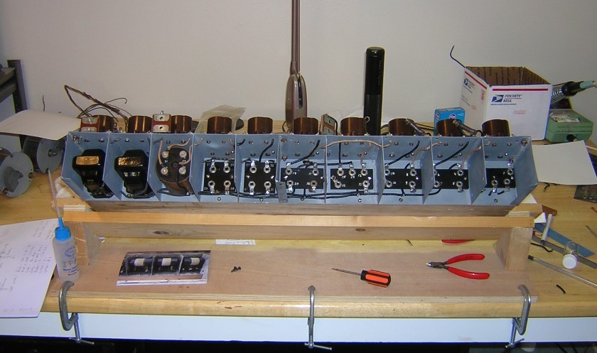
This photo shows the rebuilding process of the cleaned transformer shielding assembly. The tube sockets and other parts were completely disassembled and cleaned. A wooden jig was built to hold the assembly in an upright position for rewiring. I wore cotton gloves during this process to prevent oil from my fingers contaminating the metal.

Another view of the transformer shielding assembly. Three of the brackets on the bottom of the assembly were broken off and they needed to be re-soldered.

Here is a view of the front of the metal transformer shielding assembly. The original wiring was saved as much as possible. Detailed photos were taken of the entire assembly before it was taken apart to aid in reassembly. Every wire was marked with tape.

The above photo shows the transformer shielding assembly and numerous removed parts. I thought of several different ways to clean the metal and ultimately decided that it would be best to grit blast it. Grit blasting would remove the corrosion and leave a uniform texture to the metal.


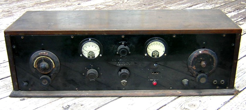
These two photos show the C-10 as it was when I purchased it. Several parts were missing, including both panel meters and a multi-function switch for the right meter. The cabinet was broken in the rear and the right front corner of the base was broken off. One audio transformer was missing and the filter transformer had two broken terminals.
The metal shielding for the transformers and the capacitors was very dirty and there was several areas of corrosion. The entire assembly would have to be disassembled to get it clean. The lettering on the front panel was painted and it needed to be restored.
January 7, 2011 update: Leutz C-10 restoration
E.I.S. advertisement for the Navy Model C-10 superheterodyne from the June, 1925, Popular Radio magazine.

|
Type |
Peak Freq. |
Lower 3 dB |
Upper 3 dB |
Bandwidth |
Relative gain |
Pri. ohms |
Sec. ohms |
|
#1, E.I.S |
38.8 KC |
20.2 KC |
67.6 KC |
47.4 KC |
15.7 |
149 |
485 |
|
#2, E.I.S |
38.3 KC |
20.9 KC |
67.8 KC |
46.9 KC |
18.0 |
162 |
498 |
|
#3, E.I.S Filter |
39.1 KC |
35.0 KC |
44.1 KC |
9.1 KC |
12.4 |
60 |
1.37 megohms |
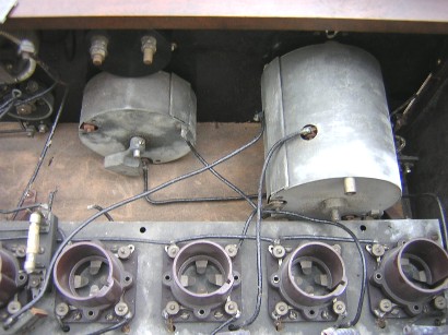
The untuned IF transformers are enclosed in metal cans but the filter transformer (marked output coupler in the above schematic) is enclosed in some type of phenolic can with formica endplates. Two terminal studs on the filter transformer were broken when I got the receiver so I had to disassemble the transformer to repair it. The filter transformer assembly contains a tuning capacitor in parallel with the primary coil and a parallel combination grid leak resistor and capacitor in series with the secondary coil. Specifications show that the IF frequency for the C-10 was 47 KC. However, my C-10 IF transformers peaked at near 39 KC.
I had the filter transformer disassembled so I was able to make tests on the individual capacitors and inductors. The primary capacitor was marked .01 mfd (matching the prints for the C-7 and the C-10 superhets), but it measured .003 mfd? The transformer was already peaking at a lower than spec frequency and if I increased the capacitor to a .01 mfd it would lower the peak frequency even more. Both internal capacitors were checked for leakage and they were both good. Since all three IF transformers peaked at near the same frequency I left the primary capacitor alone. The actual resistance of the secondary winding was 459 ohms, but the secondary winding measures 1.37 megohms on its terminals because of the internal grid leak resistor.
Schematic of the Navy Model C-10 as taken from Modern Radio Reception. My set was wired slightly different, perhaps more like the schematic on Nostalgia Air as seen here.

Antenna tuning capacitor and three-ganged TRF capacitor.

Inside view of the filter transformer.
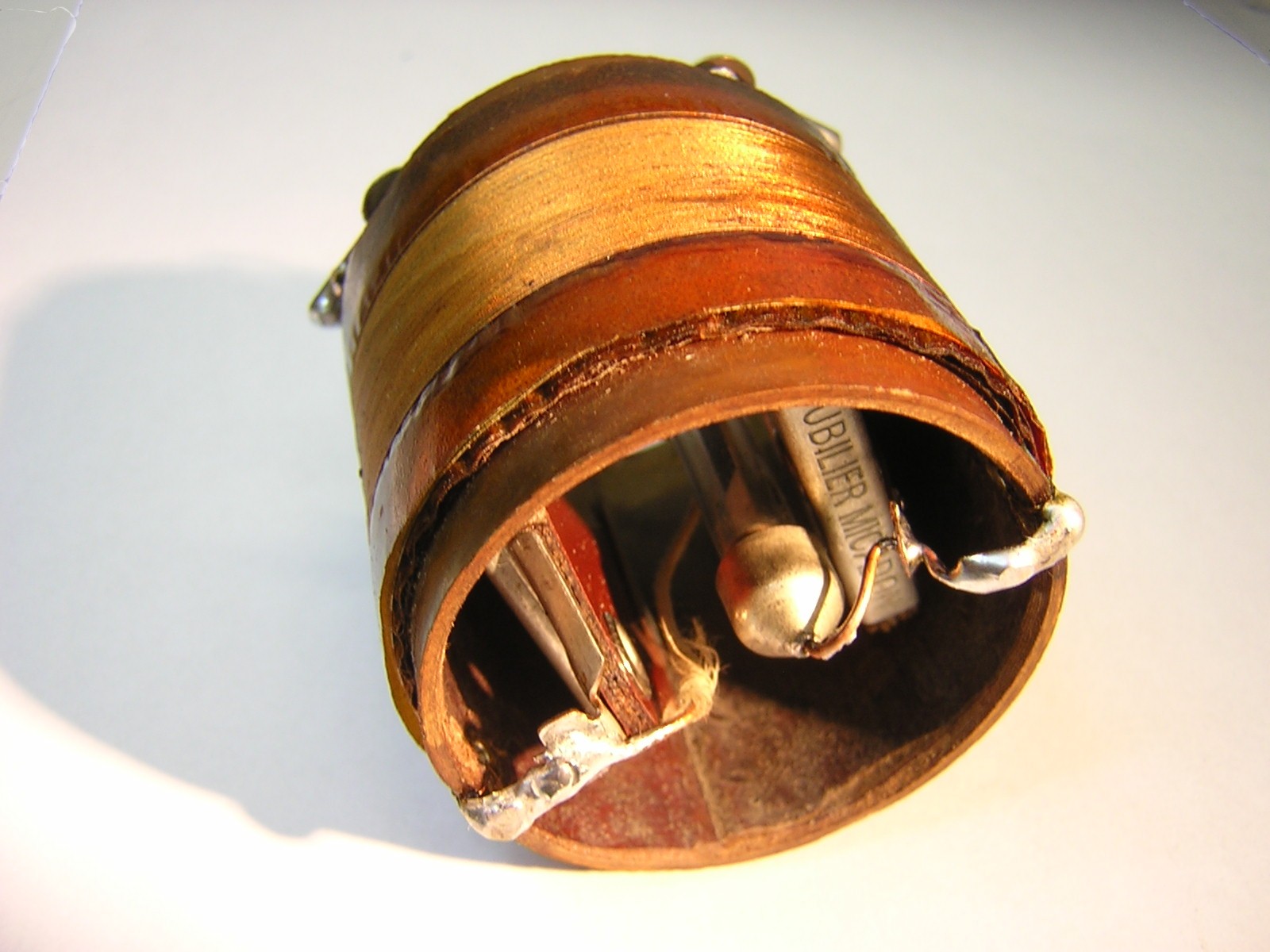
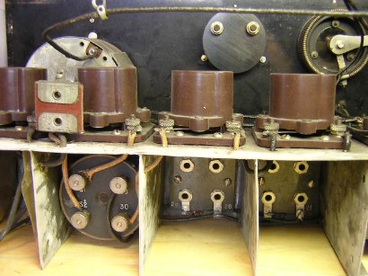
Interchangeable TRF transformers for the C-10.


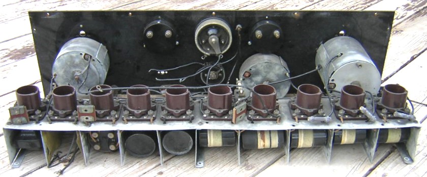
Rear angle view of my set. The transformers for each stage have their own shielded compartment. Going from the right to left with this view: antenna coupler, TRF transformer, TRF transformer, oscillator coupler, TRF transformer, IF transformer, IF transformer, filter transformer, audio transformer (missing), and audio output transformer. The various TRF and IF transformers were factory manufactured. I don’t know who else would have made and supplied them if it wasn’t E.I.S. Most of these transformers are plug-in units and they have numbers that match numbers on the sockets. I have three different sets of the TRF transformers and oscillator couplers to cover different bands. This was a radio that was made from some type of kit.
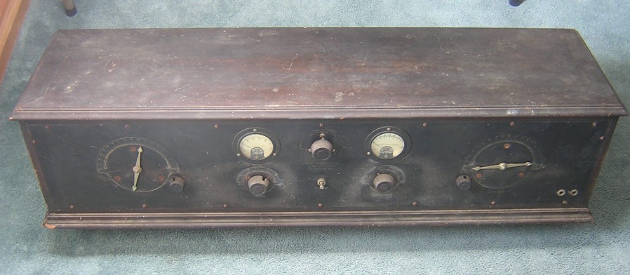
This is another Leutz radio that I plan on restoring some day. It’s a Navy Model C-10. There are several different variations of the Navy Model C-10, mine being the lowest quality one I’ve seen. But it is a C-10, and I’m lucky to have found it! I don’t think the tuning dials are original to this set, because there are small holes above each dial that were made for another style of dial (I suspect the National Type B). The main tuning dial on the left controls three ganged capacitors. Another tuning capacitor (which tunes the antenna) is located to the lower right of the main tuning dial. The oscillator tuning dial is on the right. This set is a three-dial superheterodyne that uses five different tuning capacitors. Here are a few particulars of my set:
1. The radio uses three stages of Tuned Radio Frequency (TRF) amplification ahead of the first detector. It is a combination TRF superhet. In other words, a switch on the front panel converts the set from a five or six tube TRF receiver into a nine or ten tube superheterodyne receiver. The combination feature dates this set to about 1926.
2. The front panel measures 28 1/4” long by 8” high by 3/16” thick.
3. E.I.S. oscillator coupler, filter transformer, IF transformers, and RF transformers.
4. General Radio tuning capacitors and rheostats.
5. Benjamin tube sockets.
6. Weston Type 301 panel meters.
7. Ten tubes.

The photos above show the original C-10 that Charles R. Leutz built in 1924 for the Montauck Point Installation. The photos came from page 133 of Leutz’s classic 1924 book Modern Radio Reception (1925 second edition). Below is a rear angle view from page 135.

IF transformers (filter on the far left).
Another view of the IF transformer compartments.
Oscillator tuning capacitor with shielding removed.
November 15, 2015 update:
I was in my back yard doing some yard work in early October and I got the following e-mail on my cell phone: “Do you buy these radios? Thanks, Marika” I thought that someone had seen my web site on 1920s superheterodynes and was wondering if I bought them. I replied back: “Yes, if it’s one I like. What do you have?” A few hours later I checked my e-mail on the computer in the house and noticed that I had another e-mail from Marika: “I can send more photos if you like.” I didn’t notice on the cell phone that the original message had an attachment. I immediately opened the attachment from the first e-mail and I saw this:

WOW!!! What I was looking at was one of the highest class Navy Model C-10 Super-Heterodynes that I had ever seen! It was somewhat dirty but it looked like it had a lot of potential. Marika owned an antique shop on Shelter Island, NY, and I assumed that this radio was brought in on consignment from a customer. I would find out later that that was not the case.
Front view of the Navy Model C-10 Super-Heterodyne, number 3! This is a massive superhet. Its front panel measures 40” long by 8” high and it weighs in at 60 pounds. It’s quite dirty and it probably needs some cleaning. I do think it would clean up fairly easy and look real nice. However, I do not have any plans to clean this old radio one tiny bit. After all, how many times do you come across a Leutz Navy Model C-10 Super-Heterodyne that is totally original, untouched, unrestored, and unmolested? It’s got some character. It took 90 years for this Holy Grail to acquire its dirt, grim, and patina. I am not going to change it.
Top angle view looking from the front of the radio. The entire inside surfaces of the radio are shielded, including the bias batteries and the bypass capacitors.
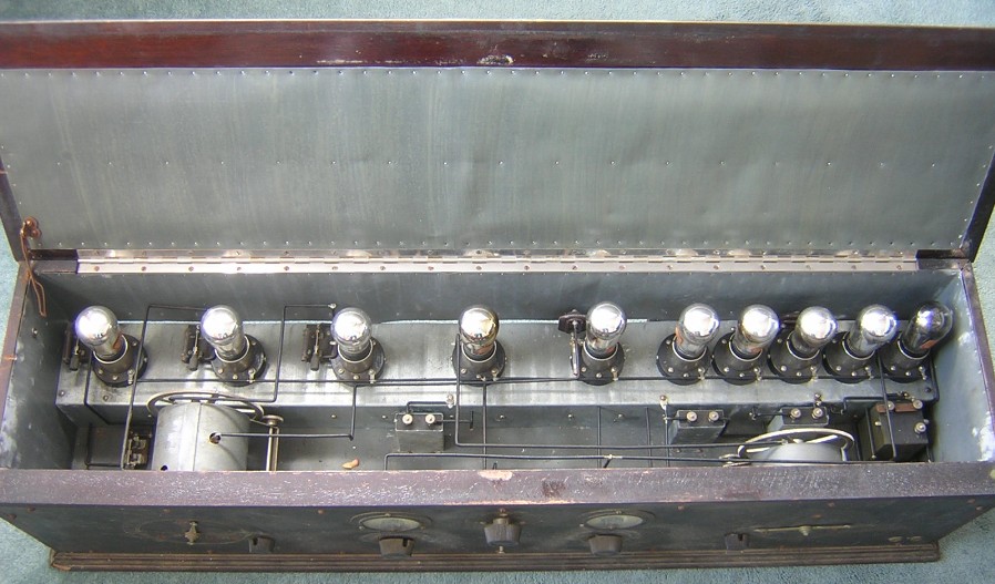

Top angle view looking from the rear of the radio.

Close-up view of the shielded oscillator capacitor. This capacitor is the main tuning control on the right side of the radio (while looking at the front of the set). The radio actually has three tuning controls that help tune in a station.
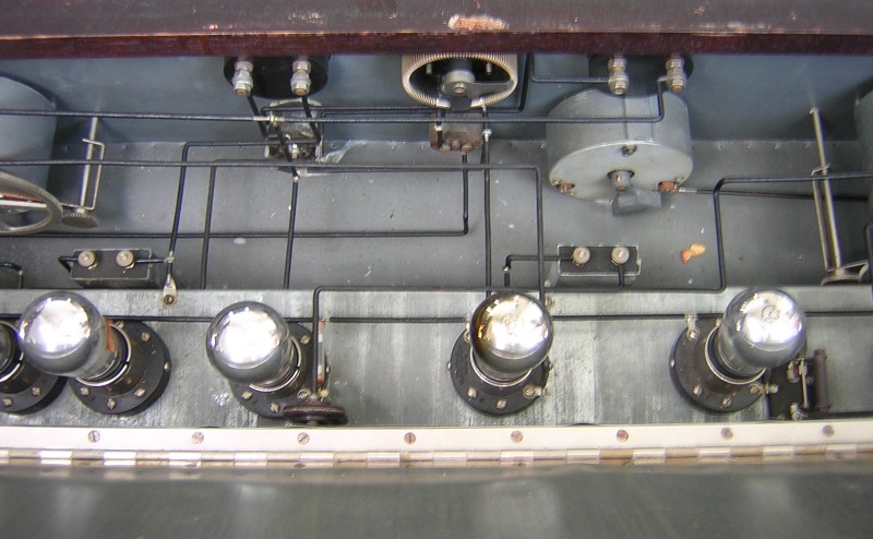
Close-up view of the center section of the radio. The shielded single capacitor in the upper right tunes the first RF transformer associated with the antenna. It is one of the three tuning controls that tunes in a station, but it has a minor effect compared the main 3-gang wavelength and oscillator controls. Note how precise all the 12-gage wiring is. Leutz did not advertise complete superheterodynes for sale because it was illegal, but I do think that this radio was manufactured in the Leutz shop.

Close-up view of the shielded 3-gang TRF capacitor. This 3-gang capacitor is one of the two main tuning controls of the radio (the left side control when looking at the front of the radio).

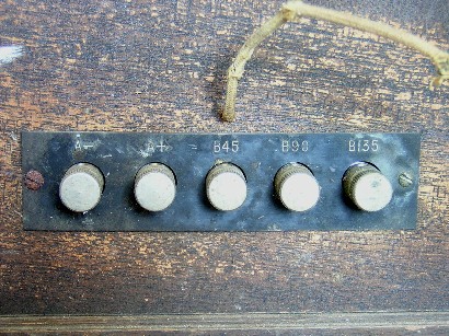
At the left: The first three RF stages have nice little knife switches across the grid resistors. The resistors are shorted out in this photo. At the right: The battery terminal strip in the rear of the radio. I believe the 135 volt terminal was meant for a 201-A tube in the last audio stage, because power tubes were not available when this set was made. One of the first power tubes, the UX-112, was introduced in November, 1925. The set had a UX-171-A power tube in the last audio stage when I got it.

Rear view of the set showing the five interchangeable coils. I don’t think this set had an opening in the back like this when the set was made by Leutz. I think someone cut this hole afterwards to get easy access to the coils. It looks like there may have been a wood door at one time but it was missing when I got the set. So much for being unmolested.
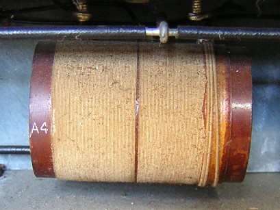

At the left: Close-up photo of the third TRF transformer, marked “A3.” At the right: Close-up photo of the oscillator coupler, marked “A4.”

Close-up view of the wavelength tuning dial on the left side of the panel.

Close-up view of the “Navy Model C-10 Super-Heterodyne” engraving. The dirt on the panel would clean off real easy.
I have seen photos of two other Leutz C-10 superhets with the 40” by 8” panels. The first photo was from an article about Charles R. Leutz in The Antique Radio Gazette, Vol. 5, No. 4, 1977 (by John H. Caperton). The second photo was of a set owned by M. Molnar. Niether one of these sets had the “Navy Model C-10 Super-Heterodyne” engraving on the front panel. For all I know the two sets could be one and the same. However, I don’t know what to make out of the fact that some sets have the engraving and some sets do not.
RCA sued Leutz in 1924 for selling complete superheterodyne kits. The only thing that Leutz could do with the superheterodyne after being sued was to sell superheterodyne plans and parts. It could be that the early C-10 panels had the engraving and the later C-10 panels did not. Leutz may have omitted the engraving on the later panels so as not to attract the attention of RCA. My Leutz C-10 has a milliamp meter with serial number 287058, and the Molnar set has a milliamp meter with serial number 1775504, indicating my set is indeed an earlier set.
There are a few clues as to the manufacture date of my Leutz C-10. The first clue deals with the length of the panel. In the May, 1925, Popular Radio, Leutz was advertising “The New Navy Model C-10 Super-Heterodyne” with a “Panel Size Only 28 3/16” by 8”.” It seems logical that most of the sets with 40” long panels were made before the length was standardized at 28 3/16” long. There could have been a small number of the longer panels in stock in May, 1925, so that date would not be a sharp cutoff date. Also, some customers may have actually wanted the longer panel instead of the shorter panel.
A second clue of manufacture date is the fact that my set has Sangamo mica capacitors. The Sangamo mica capacitors were also introduced in the May, 1925, Popular Radio (info courtesy Bob “radious” on the Antique Radio Forum). The length of the panel and the Sangamo capacitors indicate that the set was made somewhere around May-June 1925, at the earliest.
A third clue of manufacture date, of perhaps minor significance, is the battery terminal strip in the rear of the cabinet. The C-10 schematic diagram in Modern Radio Reception (shown above) shows a 90 volt maximum voltage associated with an 01-A output tube. Was the 135 volt battery terminal on this set designed for a power tube instead of an 01-A? One might suspect something like that, until they notice that the C-10 that Leutz built in 1924 has five terminals for the battery connections, just like this set has.

Marika gave me some historical information on this 40-inch C-10: “I do not have much history because it was my father’s and I cannot ask him because he is not here to ask. He lived to be close to 90. . .died over 10 years ago. . .My father was a seaman and loved many gadgets especially communication ones. If I come across anything else of interest I will email you. Although we live on Shelter Island he spent much time in Montauk. Always lived on an island. Was born in Saarema, Estonia. . .also an island. . .came to the U.S. in the 40’s and my memories of him are always on some sort of boat. . .especially sailing.”
December 8, 2023 Update:
C-10 number 4
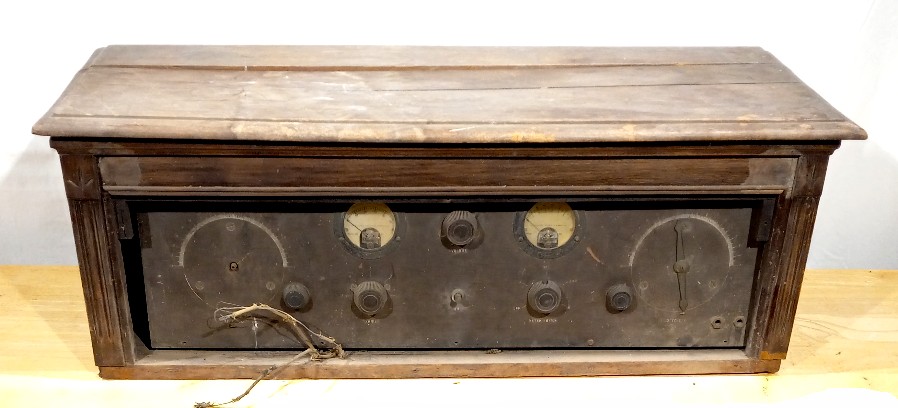
As-purchased photo of a Leutz Navy Model C-10, number 4! This was a basket case radio when purchased. I figured that the set had a lot of potential, and the price was right, so I bought it. The wood cabinet was in horrible shape: the complete base molding was missing, the lid was warped and split into three sections, and the entire cabinet was starting to come apart. Not to mention the mud dauber nests all over the place. The front panel had a lot of sun oxidation. I promise I am not going to buy another one of these!
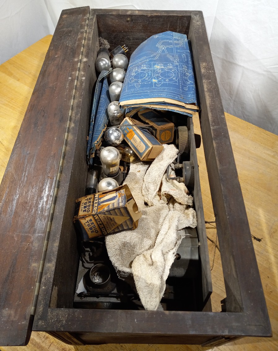
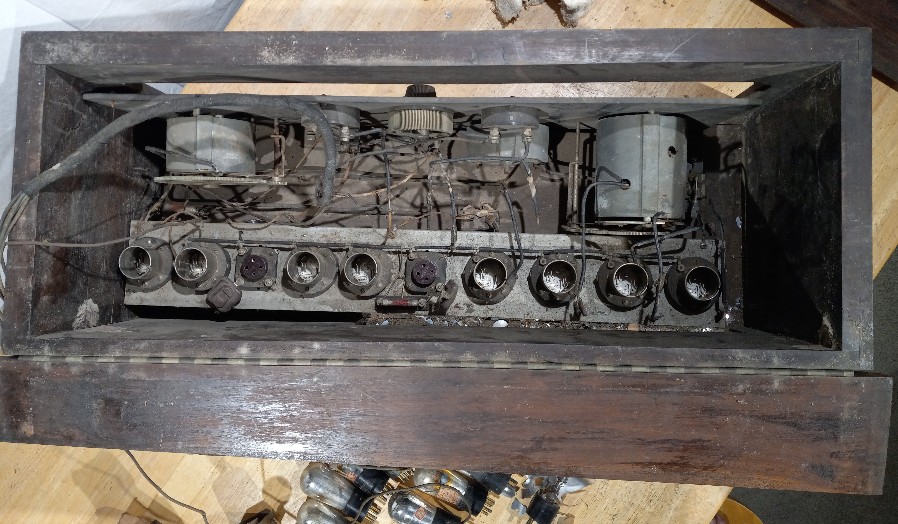
As-purchased photos of the C-10. The one best thing about this set was the fact that the electronic components were complete. The entire set needed extensive restoration but all the parts were there. That is saying quite a bit, because some of the parts would be “unobtainium” to locate.
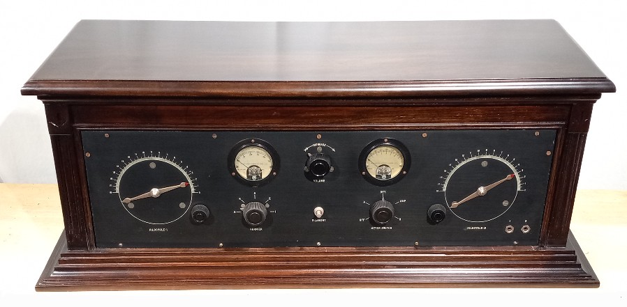
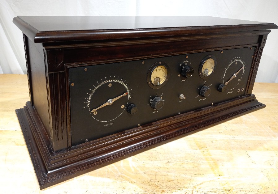
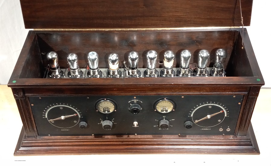
Front view of the restored Leutz Model C-10 Super-Heterodyne. Some people may think that this is a Norden-Hauck version of the C-10 but I don’t think this is so. This is not a radio that was built by Norden-Hauck. It is a Charles Leutz design and I believe the parts were purchased from EIS.
I fabricated a new lid that was made like the original lid. I also made the base molding. I had no idea what the original molding looked like. I made the base molding fairly large because the top of the cabinet is fairly large and it balances out the design.
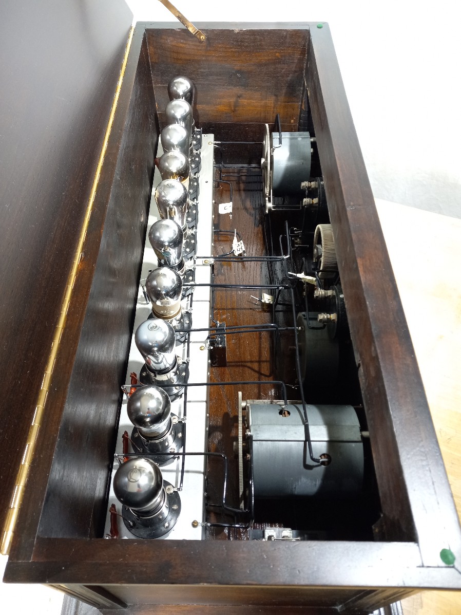
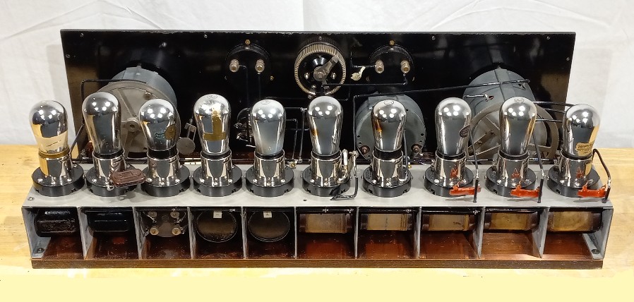
Rear view of the chassis. When I purchased this radio it had two General Radio 371 IF transformers installed in the compartments before the Leutz filter transformer. I thought that this was probably ok. It’s probably what Leutz would have recommended as a replacement transformer. I did a pass band measurement of the transformers and decided that they are terrible transformers! These things peak at 20 kHz and they pass frequencies well down into the 10 kHz range! I had measured one of these transformers before and thought that my one example was just a poor fluke. Nope. I have measured three of four of these General Radio transformers now and they are all repeatable at peaking near 20 kHz. The IF transformers in the above photo were provided by Leutz. They do not have a makers mark but they look like the later style C7 plug-in transformers.
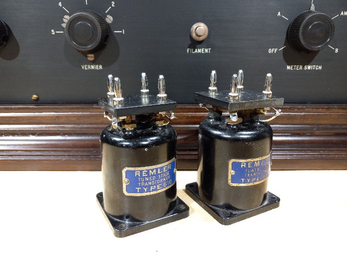
I modified these two Remler 610 IF transformers to replace the General Radio 371 IF transformers. These transformers peak at 45 kHz with the addition of a 250 pF capacitor of the secondary. The filter transformer in this particular C-10 was peaking at 37 kHz. I was able to put a 390 pF capacitor on the secondary of the Remler 610 transformers to get them to peak at 37 kHz. Warning! Do not attempt to do this yourself!! When I first tried operating this C-10 I had uncontrollable oscillations. I tried all kinds of things to try to get the set to stop oscillating. In the end I was left with one tube installed in the first detector socket of the radio that was oscillating. Just one tube driving the primary of the first Renler 610 and that was all it took! I replaced the Remler 610 with a wider bandwidth Leutz transformer and it cured the oscillation problem.
.