Madison-Moore “One-Spot” IF Transformers

One of the main objections with the early superhets was that a station could be tuned in at two different settings on the oscillator tuning control. Why did this happen? Because the IF frequencies in the early superhets was very low, sometimes just barely above the audible range. Consider the case of a superhet with a 30 KC intermediate frequency. If the loop control was set to receive a station at 1000 KC (near the middle of the AM band), an oscillator frequency of either 1030 KC or 970 KC could be used to mix with the signal and produce an IF of 30 KC. In this example, the two spots on the oscillator dial are separated by only 60 KC. That separation is a small percentage of the standard broadcast band (550 KC to 1500 KC in 1927), which means that most of the stations will tune in at two different spots on the oscillator dial.
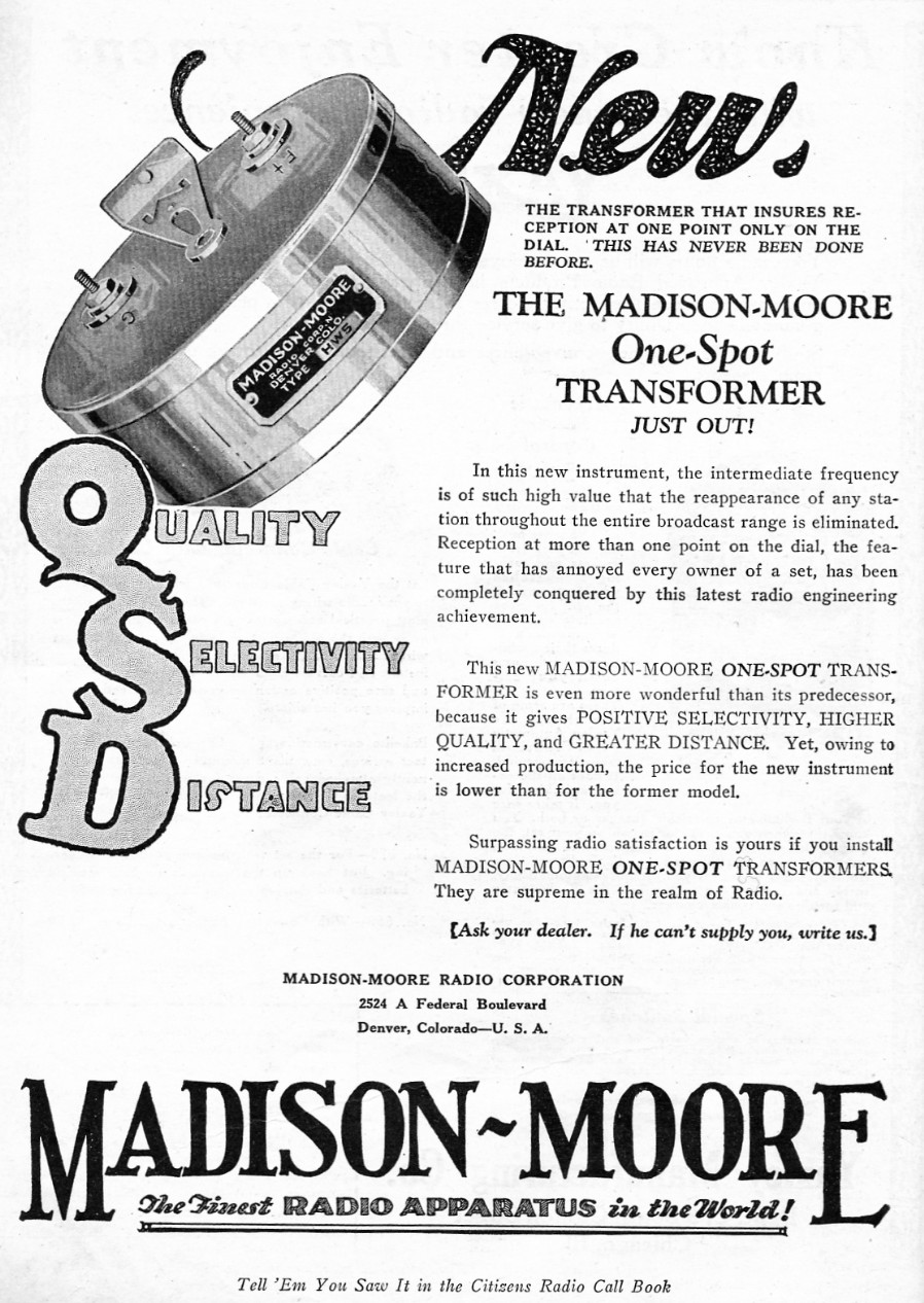
If we increase the intermediate frequency to 100 KC, then the two spots on the oscillator dial are shifted to 200 KC apart. If we increase the intermediate frequency even more to 500 KC, then the two spots on the oscillator dial are shifted to 1000 KC apart. That separation is a significant percentage of the entire broadcast band, and it effectively shifts the second spot on the oscillator dial completely off the dial! This is the principle of operation of the Madison-Moore “One-Spot” IF transformers.
I no longer own a Madison-Moore superhet but I measured the bandpass properties of the “One-Spot” transformers and have included the data here. The basic “One-Spot” kit consisted of one Type HW1 oscillator transformer and four Type HW2 through HW5 IF transformers. The oscillator was designed to produce a frequency from 1040 KC to 1990 KC and the IF transformers were designed to have a maximum peak at 490 KC.
Two different frequency bands can mix with the oscillator frequency to produce an IF frequency of 490 KC. The lower band is determined by subtracting 490 KC from the oscillator frequency, and this band turns out to be 550 KC to 1500 KC, the standard broadcast band. The upper band is determined by adding 490 KC to the oscillator frequency, and this band turns out to be 1530 KC to 2480 KC. Notice that there is only one spot on the oscillator dial that will tune in any particular station in the lower band (the broadcast band). The upper band is completely out of the broadcast band and it is rejected from mixing with the oscillator by the main RF tuning control.
When I first measured the frequency response of the Madison-Moore IF transformers I thought that there was something wrong with them. I was expecting a peak near 100 KC, but these things didn’t peak until around 490 KC. Also, the gain per stage was much lower than any other transformer I had ever measured, about 1/3 as much. I suspected that a capacitor inside the transformers may have opened up to produce the higher peak frequency. However, an examination of two of the transformers convinced me that there was nothing wrong with them. Much of the mystery was solved when Richard T. Ammon informed me that the transformers were the new “One-Spot” transformers. A schematic of a later version Madison-Moore “One-Spot” superheterodyne (using AC tubes and special “One-Spot” IFs) can be found on Nostalgia Air here.


Inside view of the Type HW2 IF transformer.

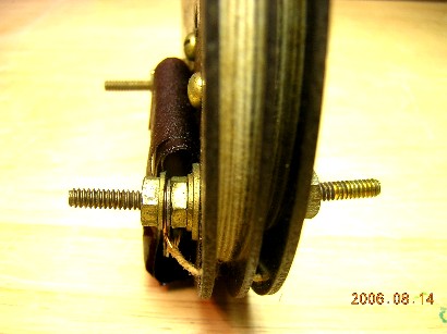
Inside view of the Type HW4 IF transformer.
The low relative gain of the high frequency “One-Spot” IF transformers is most likely due to the limitations of the 01-A triode tubes at the higher frequency. The “One-Spot” superhet probably needed a few more stages of RF amplification compared to the normal 01-A superhet of the day. Most manufacturers increased their IF frequencies into the 400 KC range after the invention of the screen grid tube in December, 1927. The screen grid tube had a much higher gain than the 01-A triode tube, and it amplified higher frequencies a lot better.
November 7, 2012 update:
Madison-Moore One-Spot Superheterodyne
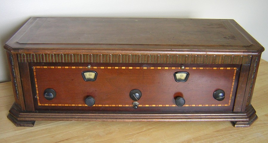
I purchased this beautiful Madison-Moore One-Spot superheterodyne at a Mcmillan Brothers Auction in Mount Vernon, Washington, on September 30, 2012. The radio is in excellent condition and it was patterned after a construction article in the December, 1926 Citizen’s Radio Call Book. Here are a few particulars of this set:
1. The front “Lignole” panel measures 26” long by 7” high by 3/16” thick. The Lignole panel was specified in the December, 1926 CRCB construction article.
2. Madison-Moore Type HW One-Spot IF transformers.
3. Hammarlund tuning capacitors.
4. Marco illuminated tuning dials.
5. Carter rheostats and potentiometer.
6. General Radio audio transformers.
.
Harry Madison
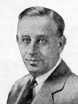
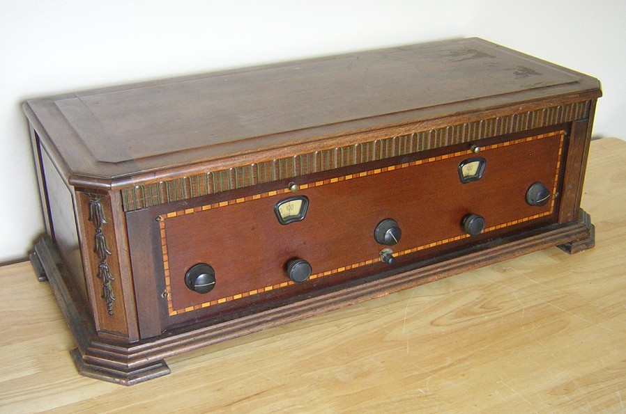
Photo of the Madison-Moore One-Spot, as copied from the December, 1926, Citizen’s Radio Call Book. My set looks nearly identical, except for the addition of a small knob and the missing writing on the front panel. Those little nubs above the main tuning dial windows are actually switches that control the lights on the illuminated dials. The Marco illuminated dials are high quality and very smooth in operation.

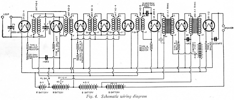
Schematic diagram of the Madison-Moore One-Spot superheterodyne from the December, 1926, Citizen’s Radio Call Book.
An under side chassis view.
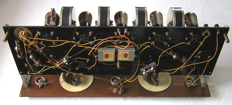
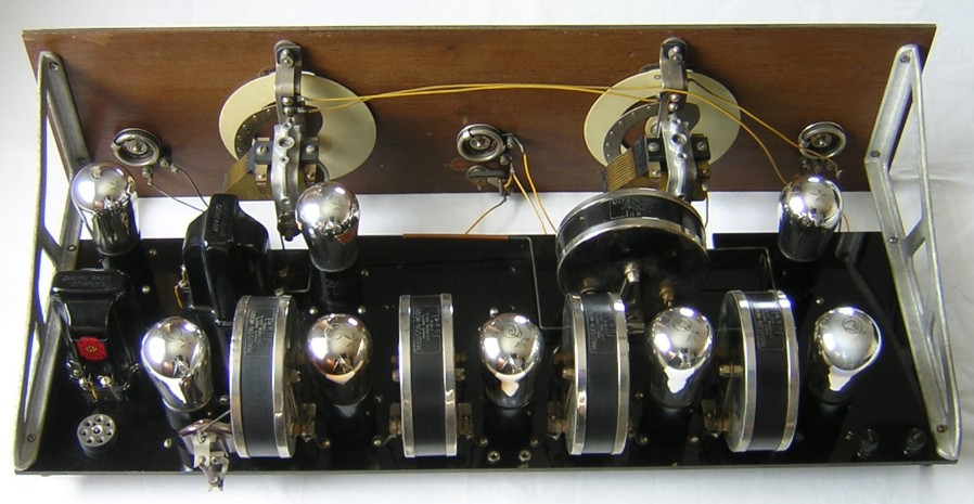
Rear angle view of the chassis. This set was professionally made.
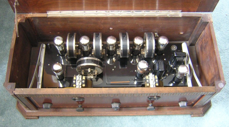
Inside cabinet view of the chassis.
Advertisement for the Madison-Moore HW series “One-Spot” IF transformers as copied from the December, 1926, Citizens Radio Call Book.
|
Type |
Peak Freq. |
Lower 3 dB |
Upper 3 dB |
Bandwidth |
Relative gain |
Pri. ohms |
Sec. ohms |
|
HW2 |
489 KC |
475 KC |
505 KC |
30 KC |
3.45 |
0.8 |
4.1 |
|
HW3 |
503 KC |
488 KC |
519 KC |
31 KC |
2.5 |
0.7 |
1.1 |
|
HW4 |
488 KC |
474 KC |
503 KC |
29 KC |
2.65 |
0.7 |
1.1 |
|
HW5 |
492 KC |
477 KC |
507 KC |
30 KC |
2.45 |
0.6 |
1.0 |
Another inside view of the HW2 IF transformer.
Another inside view of the HW4 IF transformer.