Pressley/Sangamo

The Pressley superheterodyne was developed by Jackson H. Pressley, Chief Engineer of the Signal Corps radio laboratories at Camp Vail, New Jersey. The receiver incorporated a new balanced bridge oscillator/first detector circuit that would prevent radiation from the loop antenna. This was somewhat of a major breakthrough because radiation was one of the biggest complaints of the early superhets. The construction article for this receiver appeared in the December, 1924, Popular Radio magazine. Here are a few particulars of this set:
1. The circuit uses a special balanced bridge oscillator/first detector to prevent radiation.
2. The front panel measures 18” long by 7” high. The cabinet is 27” long.
3. The front panel is engraved with a likeness of Albert Einstein and the cabinet is personalized with a large “M” on each side.
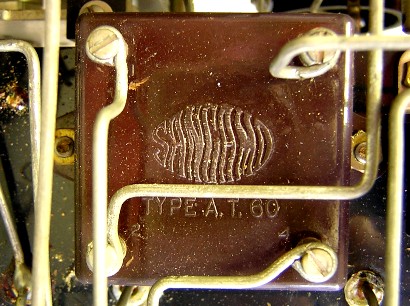
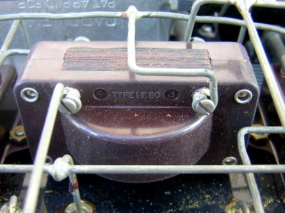
4. Sangamo IF transformers (AT-60 and IF-60) and Sangamo oscillator coil.
5. Benjamin seven socket shelf with seven Benjamin tube sockets.
6. Cardwell tuning capacitors.
7. Weston panel meter
8. Thordarson audio transformers.
Sangamo advertisement from the January, 1925, Popular Radio magazine.

|
Type |
Peak Freq. |
Lower 3 dB |
Upper 3 dB |
Bandwidth |
Relative gain |
Pri. ohms |
Sec. ohms |
|
#1, AT-60 |
65.4 KC |
58.8 KC |
72.7 KC |
13.9 KC |
5.3 |
35.2 |
37.3 |
|
#2, IF-60 |
41.0 KC |
8.3 KC |
220 KC |
211.7 KC |
7.4 |
143.4 |
147.4 |
|
#3, AT-60 |
64.7 KC |
58.5 KC |
71.9 KC |
13.4 KC |
5.3 |
35.5 |
36.8 |
|
#4, IF-60 |
47.5 KC |
11.2 KC |
219 KC |
207.8 KC |
6.5 |
155.3 |
137.5 |
The air-core AT-60 transformers are narrow-band and the iron-core IF-60 transformers are wide-band. The peak frequencies of the two types of transformers are different; the AT-60 peaks at about 65 KC, while the IF-60 peaks at about 44 KC. There shouldn’t be a problem with the peak frequency offset because the bandpass of the IF-60 transformers covers the entire bandpass of the AT-60 transformers. The IF frequency of the entire chain is controlled by the narrow-band AT-60 transformers at 65 KC.
The Sangamo IF transformers were probably the first set of IF transformers that were designed to peak at two different frequencies. The two-frequency design may have just been a fluke, or a byproduct of some other desired result. The Lincoln IF transformers from a few years later had a similar design.
The table below lists the bandpass measurements of the IF transformers. The first three transformers were measured with the secondary winding referenced to A-. The last transformer (type IF-60, feeding the second detector) was measured with the secondary of the transformer referenced to A+ and the grid leak resistor and capacitor in place.
Photo of Jackson H. Pressley at the controls of his new non-radiating superheterodyne, from the December, 1924, Popular Radio.

Schematic diagram of the Pressley superheterodyne, from the December, 1924, Popular Radio. The oscillator coil is identified at “A” and “B,” the oscillator tuning capacitor is identified at “D,” the loop tuning capacitor is identified at “C” (the loop connects to terminals 1, 2, and 3), a switch for changing wavelengths is identified at “Q.” Air-core AT-60 transformers are identified at “K1” and “K2,” and iron-core IF-60 transformers are identified at “L1” and L2.” The special oscillator/first detector balancing capacitor is identified at “E.”

1921 photo of Albert Einstein.
Front panel engraving on the Pressley.


Sangamo AT-60 IF transformer.
Sangamo IF-60 IF transformer. Note the large iron core.


Bottom view of the base panel. Notice that the four IF transformers are staggered. The first one on the left is an air-core type AT-60, which is followed by an iron-core IF-60, followed by another AT-60, and then another IF-60. This set was professionally wired.

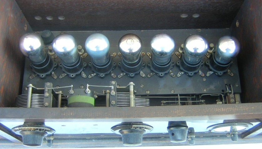
Rear angle view with the tubes removed. The oscillator coil is between the two main tuning capacitors and the balancing capacitor is below the oscillator coil. The IF transformers are located under the base panel. This is a very compact set for the day.

Top inside view.

August 7, 2018 update:

Phil Gander from Australia sent me an e-mail inquiring about the balancing capacitor in the first detector/oscillator. He wasn’t sure what capacitor, of the three variable capacitors, was the balancing capacitor, and if my set even had a balancing capacitor. I must admit that the photos presented so far do not show enough details of the capacitor to distinguish how special that capacitor really is. Check out the above photo taken from an under-chassis view.
The capacitor has two different stator sections that are insulated from each other (identified on the schematic diagram as S and S’). The rotor plates (identified on the schematic diagram as R) rotate between the two stator sections. The total capacitance between the two stator plates changes when the rotor is rotated (if the capacitance is measured from one stator plate to the other). However, the real benefit of this capacitor is that the capacitance of one stator section will increase (with respect to the rotor) while the capacitance of the other stator section will decrease (with respect to the rotor) if the rotor is rotated in a certain direction, and vice versa if the rotor is rotated in the other direction. This property really facilitates balancing the bridge. It’s a pretty cool capacitor. Thanks for your inquiry Phil!
.