Radio Instrument Company/VirBren

The Radio Instrument Company superhet shown here probably dates from the late 1923 to the mid 1924 time frame. The outward appearance of the radio was obviously inspired by the Leutz Model C design, with the layout of the two meters and the rheostats. The size of the radio is the same as the Model C also. Though not a Leutz, this radio has filled the vacancy of the Leutz set that I’ve always wanted. The original tuning knobs were probably replaced with the vernier units a few years after the radio was made. Here are a few particulars of the set:
1. The circuit is the standard 1920s superhet circuit.
2. The engraved front panel measures 40” long by 8” high by 3/16” thick.
3. Radio Instrument Company/Virbren oscillator coupler and IF transformers (with transformer sockets).
4. ShermaTran audio transformers.
5. Amsco rheostats.
6. The variable capacitors are not marked from behind so at the present the manufacturer is not known.
7. Centralab potentiometer.
8. Kellogg tube sockets.
9. Roller-Smith meters.

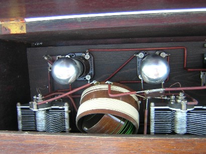
Inside angle view. The builder did a good job wiring the set.

Top view of the RF front end.

Top view of the IF amplifier.

Top view of the audio amplifier.

Close up view of the Roller-Smith voltmeter.

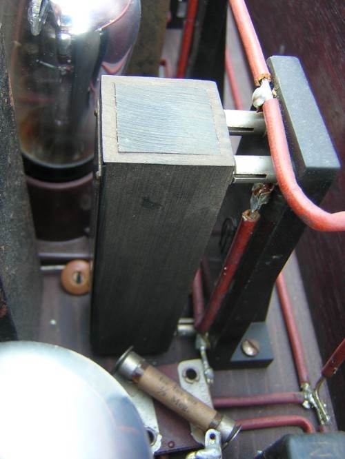
The above photo is a close up view of the #4 IF transformer mounted in its socket. The Radio Instrument Company boasted in some of their advertisements that their RF transformers were the first on the market. The first advertisement that I can find for the Radio Instrument Company RF transformers was in the December, 1921, Radio Amateur News magazine. This was one month before the RCA UV-1714 and UV-1716 transformers were advertised, so they probably had the right to boast!

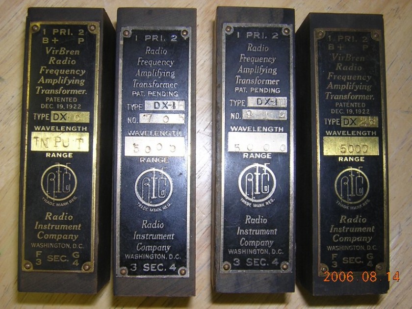
Here is a close up view of the nameplates on the four IF transformers. The first transformer (input filter) is a type DX-0 and the other three transformers are type DX-2H. Notice that the #2 and #3 transformers have serial numbers and the type number has been re-stamped from a type DX-1 to a type DX-2H. The #1 and the #4 transformers have the VirBren name. The transformers certainly look like they may have been manufactured at different times.
The input filter transformer had a .0005 mfd capacitor across the secondary winding and it peaked at 65 KC. The untuned transformers peaked at an average frequency of about 80 KC. The primary resistance of the input filter transformer was higher than the secondary resistance so I don’t know if there is something wrong with the transformer. The resistance values do seem a little odd. However, by reducing the capacitance across the secondary of the input filter transformer to .000308 mfd I was able to get it to harmonize with the other transformers. The table below lists the bandpass measurements of the transformers.
|
Type |
Peak Freq. |
Lower 3 dB |
Upper 3 dB |
Bandwidth |
Relative gain |
Pri. ohms |
Sec. ohms |
|
#1, DX-0 .000308 cap |
79.6 KC |
77.4 KC |
81.8 KC |
4.4 KC |
5.7 |
253.8 |
103.6 |
|
#2, DX-2H |
85.1 KC |
63.1 KC |
109.4 KC |
46.3 KC |
10.5 |
187.9 |
248.8 |
|
#3, DX-2H |
77.5 KC |
56.2 KC |
100.0 KC |
43.8 KC |
9.2 |
201.7 |
255.1 |
|
#4, DX-2H |
78.1 KC |
57.8 KC |
100.9 KC |
43.1 KC |
10.4 |
194.0 |
244.7 |

Radio Instrument Company advertisement from the January, 1925, Popular Radio magazine.
January 31, 2017 update:
Percival D. Lowell invented the radio frequency transformer as used by the Radio Instrument Company. The two photos below are copies of the diagrams in the original patent.


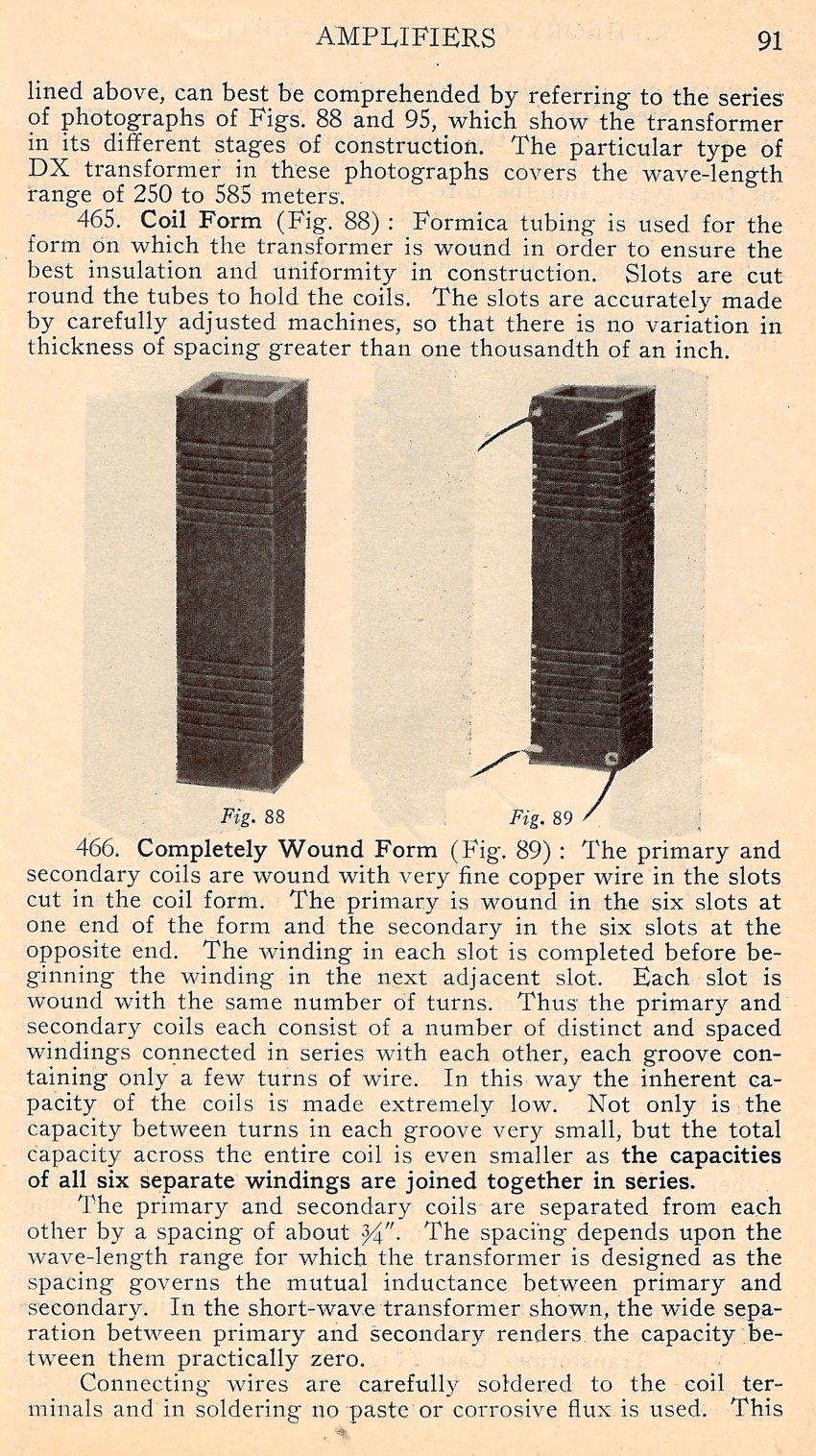
The four photos below contain a description of the Percival D Lowell transformer, as copied from the book Radio Frequency Amplification, Theory and Practice, by Kenneth Harkness, 1923.


.