Raven
|
Raven |
 |
|
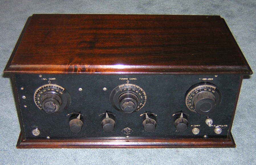
Raven Radio Inc. was a small radio manufacturing company in Albany, New York. The superheterodyne as pictured here was first offered as a kit starting in September, 1924. The radio has three large dials and at first glance it looks like a common 3-dialer TRF of the period. This radio only has two main tuning dials that tune in stations though (the large dial on the left and the large dial in the middle). The large dial on the right is not a main tuning dial as its purpose is to set the grid bias voltage on the IF amplifier stages (it controls the gain of the IF amplifier). 1. The engraved front panel measures 18” by 7” by 3/16”. |
 |
|
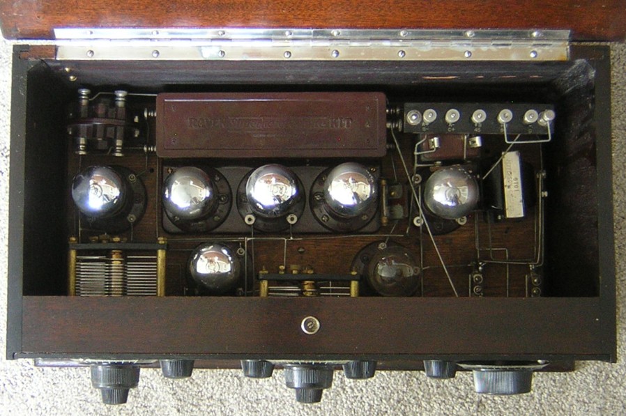
Top of the chassis inside the cabinet. The audio transformer is missing the the right side of the base board. The layout of parts is very compact. |
 |
|
Rear angle view of the chassis. |
|
|
||||||||||||||||||||||||
 |
|
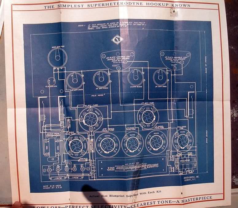
A photo of original blueprints for the Raven superheterodyne dated September 3, 1924. My set is laid out identical to these blueprints. Notice that the main tuning capacitors shown on the blueprints are the same type as in the radio. The radio was most likely assembled from a complete kit from Raven. |
 |
|
Front angle view of the Raven superhet. |
 |
|
Raven advertisement from the December, 1924, Popular Radio magazine. |
|||
 |
|||
|
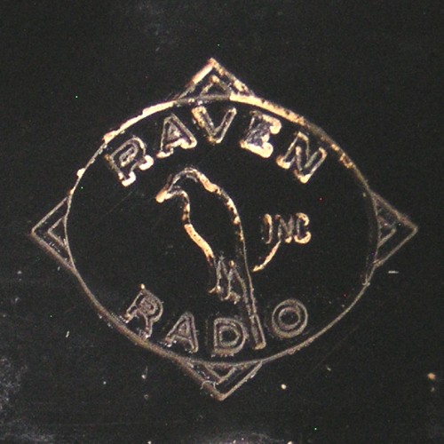
Close up view of the engraved Raven Radio logo. Most of the paint has weathered out of the engraving. |
|||
|
February 9, 2018 Update |
|||
|
I found another Raven 3-tube IF amplifier block so I decided to do some work on my Raven superhet. The first item of business was to investigate the old IF amplifier block. I wanted to learn as much as I could from that old basket case unit. The advertisement above states that the IF block is “Completely wired in Moisture Proof Wax.” Well, I don’t think that statement is entirely true after trying to melt the “wax” with a heat gun. The amber looking stuff did not want to melt and flow out smoothly at all, but rather it would just tend to stay in one spot and bubble up a little bit. It reminded me of the black tar-like substance that the Scott Selectone transformers are potted with. I suspect the substance in the Raven IF block is more like a pine tar or pitch than like a wax. |
|||
 |
|
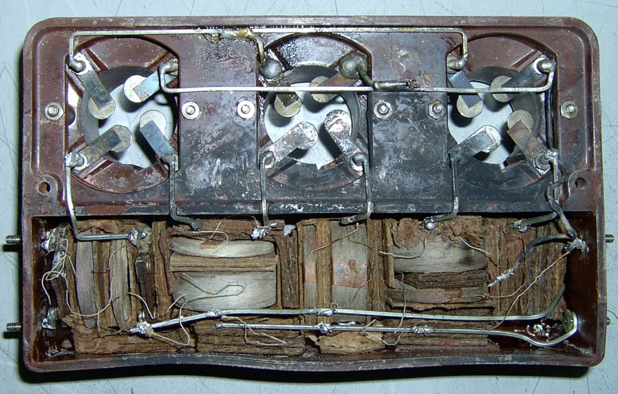
The above photo shows the Raven IF block after soaking in a small bucket of acetone for several hours. I expected to find burned up coils, but the coils had no signs at all of being burned. This is when I finally figured out the real story on the Raven IF block. Someone in the past had put this unit in an oven to try and melt out the wax to repair it. The pitch didn’t melt out at a low temperature, so the heat was raised in an attempt to melt it out and the excess heat destroyed the bakelite IF block. |
|
|
Unfortunately, the replacement IF block was not in perfect condition either. It had an open secondary coil on the last IF transformer. I am not the type of person that needs to have all of his radios in working condition. Sure, it helps if they are in good working condition, but in this case I would prefer to have an unmolested IF block that looks good than to have one that works and is all buggered up. I am happy enough to have at least three transformers that work that I can get resonant frequency data from. The table below records the pass band and resistance values of the replacement IF block. |
|
|
Note: the filter transformer (#1) was measured with terminal 2 connected to +65 volts instead of connected to the grid of the oscillator. |
 |
|
Hand drawn schematic diagram of the Raven 7-tube superheterodyne. The Raven superheterodyne IF block is shown inside the dotted lines. One thing I didn’t know about the Raven is that it is an Ultradyne. The plate supply for the first detector is taken from the grid of the oscillator tube. This is Robert E. Lacault’s modulation method of producing a beat frequency |
||||||
 |
||||||
|
Top inside view of the Raven superhet with the replacement IF block installed. WARNING! the Raven tube sockets have very stiff contact springs and it is very difficult getting the tubes in and out of the sockets. As I was trying to take one of the tubes out of a socket the tube imploded in my hand! I was very fortunate that my hand was not cut from the sharp edges of the glass. |
||||||
 |
||||||
|
One final view of the Raven superhet. I did not fill the engravings with paint. I simply waxed the panel with car wax (Turtle wax) and the engravings were filled with wax. |
||||||
|
. |
||||||