Scott World’s Record Super 8
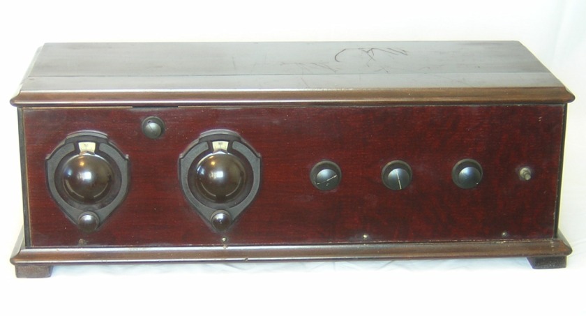
Front view of my Scott “World’s Record 8” superheterodyne. The Scott battery operated superhets are somewhat rare and highly prized by collectors. Unfortunately, my example does not have an engraved panel or the two panel meters, and the cabinet is not original to the radio. But hey, it’s a Scott, and I’m happy to have it! The radio needs a lot of cleaning and restoration work. Though the tube sockets are the UV type, which date to 1925 and earlier, I suspect that the radio itself was built in late 1926 (or thereabouts). Here are a few particulars of the set:
1. It appears to work on the standard 1920s superhet circuit.
2. The front panel measures 26” long by 7” high by 3/16” thick.
3. Scott Selectone R-400 and R-410 IF transformers.
4. Silver Marshal oscillator coupler.
5. Remler “butterfly” tuning capacitors.
6. Jefferson audio transformers.
7. Carter rheostats.
8. Mazda tube sockets.
.
|
Type |
Peak Freq. |
Lower 3 dB |
Upper 3 dB |
Bandwidth |
Relative gain |
Pri. ohms |
Sec. ohms |
|
#1, R-400 |
55.0 KC |
32.9 KC |
98.8 KC |
65.9 KC |
8.5 |
27.9 |
68.7 |
|
#2, R-410 |
49.00 KC |
46.56 KC |
51.65 KC |
5.09 KC |
12.8 |
16.5 |
535 |
|
#3, R-400 |
53.5 KC |
33.5 KC |
88.1 KC |
54.6 KC |
8.6 |
27.3 |
66.4 |
|
#4, R-410 |
48.69 KC |
46.40 KC |
51.30 KC |
4.90 KC |
13.8 |
15.9 |
497 |
I had just finished measuring the resistance of the IF transformers in my Scott WRS9 so it wasn’t hard for me to immediately notice that the resistance of the IF transformers in my Scott WRS8 were significantly different. I couldn’t imagine why there was such a large difference in the resistance of the IF transformers between the two radios. That wasn’t the biggest surprise though. The biggest surprise came when I measured the peak frequency of the IF transformers in the WRS8 - and got a value of about 49-55 KC for each transformer! It’s very strange, to say the least. And the IF transformers in the WRS8 certainly appear to be a matched set (right down to a number 36 on the bottom of each transformer).
Engineers were beginning to realize in the mid ‘20s that there were image frequency problems with the very low IF frequencies. Scott apparently was not aware of the problem in early 1926 because he went from an IF frequency of 45 KC (with the Remler transformers) down to an IF frequency of 35 KC in his early 400 series transformers. Scott must have recognized the problem sometime during the production run of the Selectone 400 series transformers, changed their internal construction, but left all outward appearances the same.
The Selectone 400 series IF transformers have at least two different peak frequencies. Early 1926 units are 35 KC and late 1927-28 units are 49 KC. It is unclear at this time exactly when the change occurred. Perhaps the only way to pinpoint a date more precisely is for people with original sets to measure the peak frequencies of the IF transformers and compare notes with other collectors.
The table below records the resistance measurements and the pass band properties of the IF transformers in the WRS8. The secondary of each transformer was referenced to A- and the grid leak resistor and capacitor of the last stage were shorted out.
December 13, 2013, update:
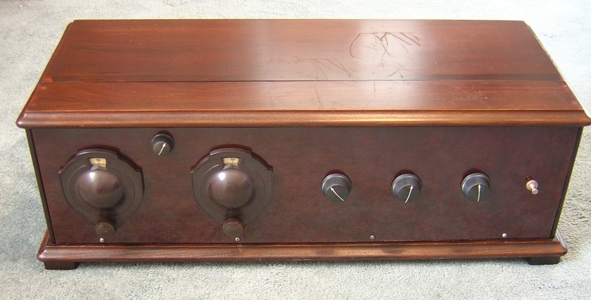
One last view of the completed receiver. I didn’t put a lot of money into the restoration effort of this radio. I mainly wanted to bring this old receiver “back from the brink of extinction,” as collector Dale Davenport would probably say. Restoration work on this receiver was completed in November, 2010.
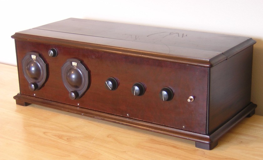
Rear view of the set. I drilled the holes in the back of the cabinet to match the location of the binding posts. The original radio in this cabinet must have had binding posts on the front panel. It would be hard to tell that this was not the original cabinet if I hadn’t already revealed it.

Front view of the completed receiver. The light from a window highlights some rather deep scratches on the lid of the cabinet.
Another inside view of the chassis installed in the cabinet.

Top view of the completed receiver with the chassis installed in the cabinet. Overall I think it turned out pretty nice.

Another side view of the completed chassis.
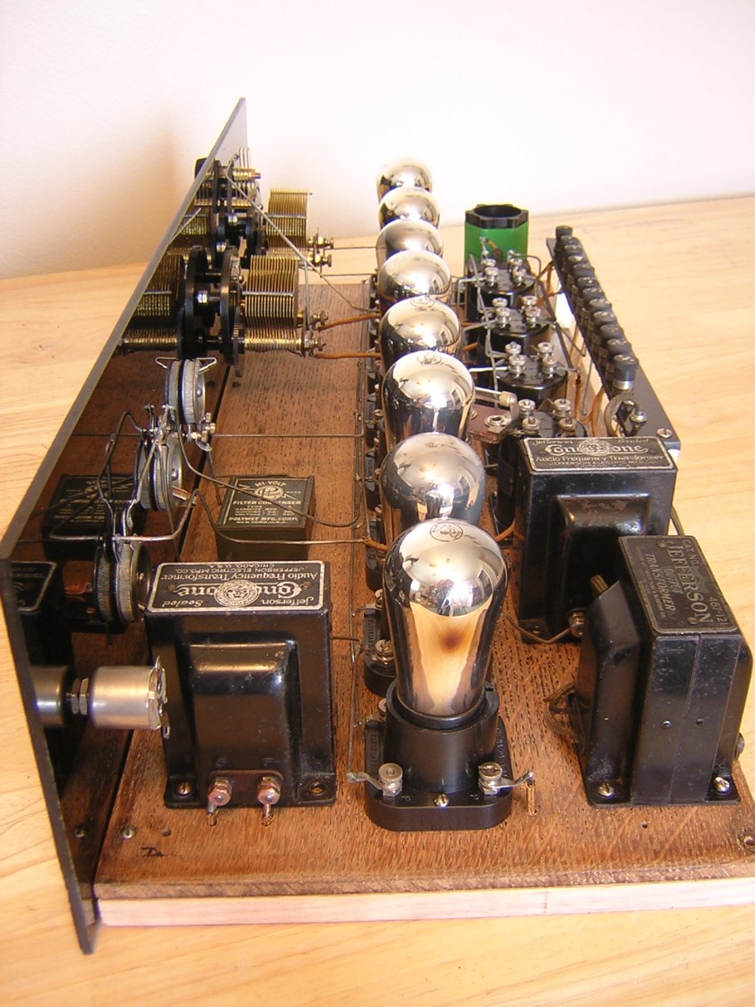
Side view of the completed chassis.
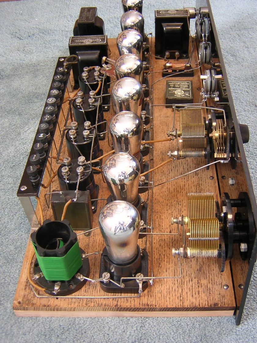
This is a rear view of the completed chassis. The radio was completely disassembled so each part could be cleaned. I used good old soap and water on the base board, along with a lot of elbow grease! Most of the parts just needed to be cleaned with soap and water. I tried to salvage most of the original wiring but some of it had to be replaced. Both of the Remler tuning capacitors were replaced with nicer units.

This is the schematic diagram for my set. I discovered that my set was wired identically to the “Scott Worlds Record Super Eight Economy Model for 1928,” as described in the November, 1927, Citizens Radio Call Book. My set was probably built in late 1927 or early 1928. The IF transformers are probably some of the last 400 series IF transformers that Scott manufactured.

One of the first things that I noticed when I started to work on the Scott was a date code on one of the Remler tuning capacitors. The last date was 2-22-27, which means that the radio was built sometime after that date. I was pleasantly surprised with the Scott Selectone transformers also. I had previously measured them and thought that the coils were all open circuited. Additional investigation however revealed that they were actually all good. A heavy patina or crust on the terminals was preventing me from measuring them correctly the first time. Each transformer was marked on the bottom with a number 36, presumably for 36 KC.


January 7, 2011, update: Scott Worlds Record restoration
Scott Transformer Co. advertisement from the September, 1926, Citizens Radio Call Book.

|
Type |
Peak Freq. |
Lower 3 dB |
Upper 3 dB |
Bandwidth |
Relative gain |
Pri. ohms |
Sec. ohms |
|
#1, R-410 |
34.4 KC |
32.5 KC |
36.5 KC |
4.0 KC |
7.9 |
21.6 |
559 |
|
#2, R-400 |
35.0 KC |
20.1 KC |
61.1 KC |
41.0 KC |
8.4 |
28.4 |
107.3 |
|
#3, R-410 |
34.9 KC |
33.1 KC |
36.8 KC |
3.7 KC |
8.6 |
21.5 |
555 |
|
#4, R-400 |
Bad trannie |
|
|
|
|
Open |
111.6 |
I have not measured the bandpass characteristics of the transformers in my Scott superhet because they are all bad. However, I have measured the bandpass characteristics on another set of Scott IF transformers that I have. Both of the R-410 filter transformers on my spare set had open windings and had to be repaired. The spare transformers were apparently an early design where the wood dowel projected some distance above the primary coil and the potting was only 1/4” thick. The coils were held in place by forcing toothpicks between the coil form and the wood dowel, as can be seen in the example above. Well, the toothpicks fell out and the subsequent movement of the coils along the wood dowel broke the tiny wires. The photo of the R-410 above shows Scott’s attempt to correct the faulty earlier design. The table below records the bandpass characteristics of the spare set of transformers.
Carter rheostats and potentiometer.
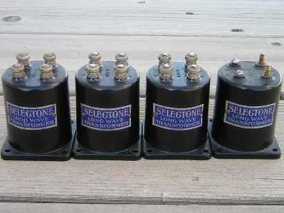
A spare set of Scott Selectone transformers.

Inside view of the Scott Selectone R-400 iron-core IF transformer. These transformers are completely potted in hard black tar or pitch. The transformer above was removed from the potting by immersing the assembly in a small bottle of acetone. The acetone dissolved the tar but left the transformer unharmed. If you repair a transformer like this you should remove the label first because the acetone will remove the paint from the label.
Inside view of the Scott Selectone R-410 air-core IF transformer. Only the bottom part is potted with hard tar (the potting on this transformer is quite thick; I’ve repaired two transformers where the potting was only about 1/4” thick). Primary is on top and secondary is on bottom. A .0085 mfd capacitor is in parallel with the 2.7 mH primary. The capacitor is mounted under the wood dowel and it is potted in this particular example.


Scott “Selectone” R-400 and R-410 IF transformers.
Jefferson audio transformers.


Remler “butterfly” tuning capacitors.
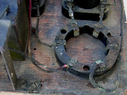
Silver Marshal oscillator coupler socket.

Top view of the chassis. Yes, it’s grimy, and it needs a lot of work.
