St. James IF Transformers & Superheterodyne

St. James Two-Forty IF Transformers

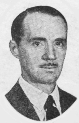
     Robert T. St. James was experimenting with radio in the early days of the “wireless” age. Bob, as his friends called him, was conducting an amateur radio station for several years prior to World War 1. With his vast knowledge of radio, he was put in command of the First Division Naval Radio School at Harvard. Some 12,000 men passed through his classes during World War 1. It was only natural that a man such as this would become president of his own company after the war; the St. James Laboratories, of Chicago, Illinois. Today, Robert T. St. James is probably best known for his superheterodyne designs, and in particular his very strange and unique glass-enclosed IF transformers.
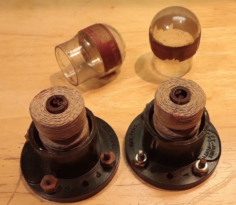
     The first style of these transformers, probably introduced before 1925, were quite colorful, having green and white coils and a red-topped glass envelope. The second style, named the “Two-Forty” (like mine shown above), were less colorful, and somewhat squatty. Both styles of transformers were vacuum processed and dehydrated before being sealed in the glass envelopes. The purpose of this special treatment was to keep moisture out of the coils, therefore their characteristics should never change with atmospheric conditions.

St. James Ad CRCB Spring 1925
St. James Red Top IF Transformers

     Above left is an advertisement for the “Red Top” transformers from the Spring, 1925, Citizen’s Radio Call Book. At right is a photo of the transformers (photo from the Internet several years ago). The peak frequency of these transformers is unknown at this time, but they were probably tuned to a frequency below 240 KC. They were advertised to be matched to within 1 KC variation.
     A new style of transformers, called the Two-Forty, were introduced in a construction article in the September, 1926, Citizen’s Radio Call Book. As the name implies, the new style of transformer was advertised to be operating at a peak frequency of 240 KC. Besides the IF transformers, there was nothing particularly special about the circuit, except perhaps for the St. James tapped oscillator coil and the St. James choke coil. The IF transformers were connected as usual, with the grid bias being furnished by a potentiometer connected between A+ and A-.

St. James 2-40 Ad CRCB Spring 1927

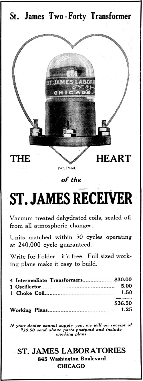
     The above scan is a very nice advertisement for the St. James Two-Forty IF transformer, as copied from the Spring, 1927, Citizen’s Radio Call Book. Note that these transformers are now guaranteed to have a peak frequency of 240 KC - matched to within 50 cycles of each other!
     I was lucky enough to recently find a set of four of the rare Two-Forty transformers, all removed from the same set many years ago(according to the seller). The seller said one of the transformers had an open secondary winding, and sure enough, when I measured that transformer on a Fluke 77, the reading briefly flashed at about 50 ohms, then it went open. It would never show any continuity on the Fluke 77 after that initial measurement. I had a hunch that the transformer may act different than expected in an actual circuit.
     This is where things get a little strange. When I did a pass band measurement on the transformers, I was naturally expecting a peak frequency at 240 KC, but these things did not peak at 240 KC at all. All four transformers actually peaked at about 355 KC! The transformer that once had an open secondary performed nearly identical to the other transformers, and it now has a stable secondary resistance of 28 Ohms. The table below shows the parameters of each transformer.

Type

Peak Freq.

Lower 3 dB

Upper 3 dB

Bandwidth

Relative gain

Pri. ohms

Sec. ohms

2-40, #1

356 KC

313 KC

400 KC

87 KC

6.6

24.7

24.6

2-40, #2

353 KC

310 KC

399 KC

89 KC

6.6

24.7

25.1

2-40, #3

357 KC

311 KC

401 KC

90 KC

6.5

24.5

24.3

2-40, #4

354 KC

306 KC

402 KC

93 KC

6.6

23.8

28.2

St. James 2-40 IF Transformer 190kc to 550kc

     The above photo is a plot of the pass band curve of transformer #1. This was produced using a different technique that what was used to get the data for the table. The data in the table is more accurate.
     So, what’s going on here? Why is the peak frequency of my transformers near 355 KC and not near 240 KC? There is a clue in the September, 1927, Citizen’s Radio Call Book. That particular issue has a construction article for a St. James “Upright Eight” superheterodyne. The set uses the Two-Forty IF transformers, but they do not mention the resonant frequency of the transformer in the article. Instead, they state this: “The transformers are tuned before leaving the factory to a specific frequency. The kit consists of four transformers that have been matched to the same frequency, which ensures maximum sensitivity. In case of accident, where replacement is needed, one of the transformers tuned to the same frequency may be obtained by mentioning the code number, which is on the transformers, when ordering.”
     Why would someone need to mention a code number when each Two-Forty transformer is supposedly tuned to within 50 cycles of each other? It is obvious that the Upright Eight model was designed for a different frequency than 240 KC. The new frequency was most likely 355 KC. Why would the St. James Laboratories not come right out and say this? It could be that they did not want their competitors to know what they were up to.

St. James Two-Forty IF Transformer

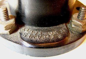
The base of each transformer is identified as a St. James Two-Forty.

St. James Two-Forty IF Transformer code

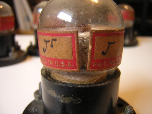
     This is the code(s) that are on each of my transformers. One side of the label has what looks like a capital letter J, and the other side of the label has what looks like a capital letter J raised to the 5th power (or it could be a large capital J with a smaller capital J above and to the right of the first). It seems to be a letter code instead of a number code. Kind of strange letters for sure, but, after all, it’s a code!

     I would be very interested to hear from anyone who has a St. James Two-Forty transformer, and to know what code is on their transformer(s).

This page was added on August 24, 2013

February 14, 2014, update:

St James former Richardson Collection

     The above photo shows a couple of old superhets that were once a part of the Billy Richardson collection. The top radio with a meter is a St. James and the bottom radio is a Lincoln. Both of the radios are somewhat rare and both were available. Besides the complete St. James radio, there was also a bunch of St. James IF transformers included with it, so that’s the one that I made a deal with. There was a good variety of St. James IF transformers here and I was very interested in doing some pass band measurements on them.

     Here are a few particulars of the complete St. James radio:

    1. The set works on the standard 1920s superhet circuit. I suspect that it dates from late 1925 to early 1926.
    2. The hard-rubber panel is 30” long by 7” high by 3/16” thick.
    3. St. James “Red Top” IF transformers, oscillator coupler, and choke coil.
    4. The tuning capacitors are unmarked, but they’ve got some cool red plastic-like insulators that match the color of the IF transformers. The capacitors have Marco vernier dials.
    5. Kellogg tube sockets.
    6. Thordarson audio transformers.
    7. Yaxley rheostat and potentiometer.
    8. Sterling volt meter.
    9. Eight tubes.

St James interior view

     Interior view of the St. James superhet. I don’t know of any other IF transformer that is more colorful than the St. James “Red Top” transformer.
     The interior layout and the wiring is in generally good condition. One of the biggest issues with the radio is the warped hard-rubber front panel. I would like to keep the panel instead of replace it. The guy I purchased the radio from said that it was very easy to straighten out the panel by clamping it between a couple of pieces of wood and putting it in an oven; when the oven and panel cool down the panel stays straight. I think I need to do a little more research on this technique. We’ll see.

     Another view of the St. James IF amplifier.

St James IF amplifier
St James Input and Interm IFs

     Close up view of the “Input” transformer (on the left, and near the second detector), and one of the “Inter” transformers. The green coil on the top is the primary coil and the white coil on the bottom is the secondary coil. The transformer marked Input has a smaller primary coil than the three transformers that are marked Inter, and the primary of the Input is tuned with a small variable capacitor.
     The words Input and Inter are very hard to see but they are in the space above the PAT. PEND. markings. I believe the number 1175, marked on all the transformers, is a serial number.
     The style of the label makes me think that these are some of the last Red Top transformers that St. James made.

     Photo of the St. James oscillator coupler and the St. James choke coil. It can’t be seen in the photo, but the St. James name is on the paper label around the choke coil.

St James oscillator coupler
St. James base board September 1926 CRCB

     The above base panel layout is copied from a construction article in the September. 1926, Citizen’s Radio Call Book entitled “The St. James Super with a New Type of Dehydrated Intermediate Frequency Transformer.” The new type of transformer in this article was the short St. James “Two-Forty.”
     This layout is very similar to my St. James superhet. My set has binding posts for connecting the batteries instead of the Yaxley cable connector, and an older style of Thordarson audio transformers, among other minor things. My set predates this set because it uses earlier parts, including the Red Top IF transformers.

St. James schematic September 1926 CRCB

     The schematic diagram of the St. James superhet as copied from the September, 1926, Citizens Radio Call Book. My set is wired very similar to this schematic. However, my set does not have the individual resistors in the filament line of the last two tubes and my set has a variable capacitor across the primary coil of the last IF transformer.

     I was a little bit disappointed when I started to investigate the IF transformers in this set. An initial check with a Fluke 77 hand-held meter did not show any continuity on any of the coils! The next step was to connect a General Radio 1862-B megger across the terminals and see what that indicated. The megger indicated continuity all right, and it actually repaired many of the coils! I suspect the magnet wire had bad connections right where the wire was soldered to the lugs and the higher voltage of the megger bridged the bad connections and at least temporarily repaired the transformers. I say temporary because I do not believe it is a good fix. I could not repair the secondary winding on the second transformer this way. The megger has two voltage settings, a 50 volt setting and a 500 volt setting, and the best that I could get the secondary on the second transformer was 20k megohms @ 500 volts. I think the transformer can be repaired by chipping out the tar in the base of the transformer and re-soldering the wires to the lugs.
     The Input transformer (#4) used a capacitor across the primary to tune the transformer. The adjustment on this capacitor was set at a minimum but the transformer was still peaking at a lower frequency that the other transformers. The DC resistance of the primary of the Input transformer seems awful low. Visually compared with the other transformers, I would have guessed the primary of the Input transformer would have been something like 80 ohms instead of 12 ohms.
     The table below records the pass band information and the resistances of the IF transformers. The secondary of the first three transformers was referenced to A-. The secondary of the last transformer (Input) was referenced to A+ and the grid leak was used.

Type

Peak Freq.

Lower 3 dB

Upper 3 dB

Bandwidth

Relative gain

Pri. ohms

Sec. ohms

#1, Inter

240.4 KC

208.7 KC

276.5 KC

67.8 KC

11.2

106.5

257.1

#2, Inter

Bad trannie


96.1

open

#3, Inter

240.2 KC

208.5 KC

273.4 KC

64.9 KC

11.4

102.4

237.6

#4, Input

233.7 KC

222.8 KC

242.2 KC

19.4 KC

12.4

12.2

248.6

St James IF transformers former Richardson collection

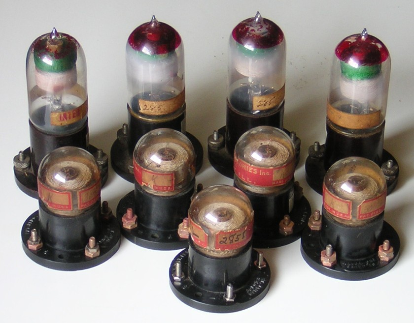
     This is a photo of the nine St. James IF transformers that came in the deal with the St. James superhet. I don’t think the four Red Top transformers were from a complete set because three were marked with a “285” and one was marked “INTER.” All the transformers were marked with the “R. T. St. James” signature, followed by a space that may have had something written but is no longer distinguishable. I believe these Red Top transformers are older than the Red Top transformers in my complete superhet. One of the 285 transformers had a broken glass support for the coils but the wires were still good. The transformer with the broken glass support (on the far right) had a similar problem with the primary coil resistance as the transformers in the complete superhet; a brief connection to the megger repaired it to the point where I could get a brief reading on the Fluke 77 before it indicated open (I suspected that it would work fine in an actual circuit where there were higher voltages involved than in the Fluke 77).
     Of the five short Two-Forty type transformers there is a complete set of four labeled with a “K” and the serial number 3042, and a single transformer labeled with an “L” and the serial number 2858. A couple of these transformers needed the megger treatment. The L transformer was missing 3 terminals when I got it and I had to add new lugs and terminals. Once the wires were soldered to the terminals the transformer was fine. All of the short Two-Forty transformers that I have measured have peaked near 350 KC. If you have transformers like this and the coils measure close to 25 ohms then you can bet that they will peak at about 350 KC.
     The table below records the pass band characteristics and the coil resistances of the Red Top IF transformers. The secondary of all transformers was referenced to A-.

Type

Peak Freq.

Lower 3 dB

Upper 3 dB

Bandwidth

Relative gain

Pri. ohms

Sec. ohms

#1, Inter

247.7 KC

216.4 KC

282.0 KC

65.6 KC

11.4

125.2

254.7

#2, 285

240.3 KC

209.6 KC

273.2 KC

63.6 KC

11.4

113.5

225.2

#3, 285

230.7 KC

202.6 KC

261.4 KC

58.8 KC

11.0

113.8

260.9

#4, 285 (with broke glass support)

248.0 KC

216.7 KC

281.4 KC

64.7 KC

11.2

open - see text above

239.2

     The table below records the pass band characteristics and coil resistances of the short Two-Forty transformers. The secondary of all transformers was referenced to A-.

Type

Peak Freq.

Lower 3 dB

Upper 3 dB

Bandwidth

Relative gain

Pri. ohms

Sec. ohms

#1, K

350.6 KC

311.9 KC

390.5 KC

78.6 KC

7.3

24.0

24.0

#2, K

349.8 KC

311.7 KC

388.1 KC

76.4 KC

7.3

24.6

24.1

#3, K

357.4 KC

312.1 KC

401.3 KC

89.2 KC

8.0

27.3

28.1

#4, K

348.2 KC

310.0 KC

388.4 KC

78.4 KC

7.3

24.7

24.0

#5, L

345.9 KC

307.3 KC

386.8 KC

79.5 KC

7.8

24.7

25.4

Robert T. St. James

Robert T. St. James

February 2, 2017 update:

St James Transformer patent diagram

Diagram of the St. James transformer from the patent office.

December 23, 2019 Update:
Additional information on the St. James IF transformers

St James transformers with top off

     This photo shows two of the Two-Forty transformers with their glass tops removed. I did not remove the glass tops on purpose; the glass was loose and they simply came apart on their own. There is no other part of the glass envelope than what you see in this photo. This type of transformer is not under vacuum. The advertisement for this transformer states that they are “Vacuum treated dehydrated coils.” The advertisement does not claim that they remain under vacuum after manufacture. Note that the coil form is phenolic

St James transformers compared

     Here is a comparison of the two main types of St. James IF transformers. Note that the coils of the Two-Forty transformer (on the left) are physically larger that the coils of the Red Top transformer (on the right). Though physically larger, the actual inductance of the Two-Forty coils is lower than the inductance of the Red Top coils because the Two-Forty coils are wound with heavier gauge wire. This makes the frequency of the Two-Forty transformers higher than the Red Top transformers.
     Note that the coil form of the Red Top transformer is glass. The glass envelope completely surrounds the coils of the Red Top transformer and the transformer is supposed to be under vacuum. The coil wires are silver soldered to larger wires inside the glass envelope, as can be seen in the photo. The Red Top transformer would be very difficult to repair if there was an open winding or a bad silver solder joint. However, I suspect most problems are with the soldered wires/connections at the screw terminals at the base of the transformer.

Silver Kit<     HOME     >Supertone

.