Leutz Model “C” IF Transformers
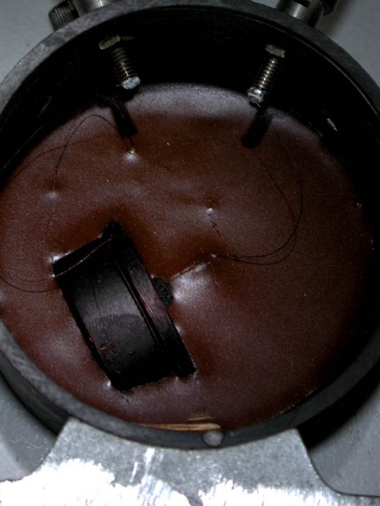
This photo is another interior view of an E.I.S. Model “C” IF transformer. The coils appear to be of higher quality than the first example shown above. The wax in this transformer is also a darker shade of brown than the wax that was in the first example. I suspect that this transformer was manufactured some time later than the first example. Photo courtesy of Norman Braithwaite.
Norman thought of a great way to open up this type of transformer for repairs: tap the transformer end-caps to determine which side has an air pocket, then drill a small hole in an inconspicuous spot and pressurize the transformer with air! The pressure inside the transformer will eventually force off one of the end-caps. Be very careful and take extra precautions so that the ejected end-cap (or other parts) do not injure other things or people!
December 21, 2012 update:
|
Type |
Peak Freq. |
Lower 3 dB |
Upper 3 dB |
Bandwidth |
Relative gain |
Pri. ohms |
Sec. ohms |
|
#1, E.I.S. Model C |
37.0 KC |
21.2 KC |
61.1 KC |
39.9 KC |
16.4 |
162 |
469 |
|
#2, E.I.S. Model C (repaired) |
35.7 KC |
21.0 KC |
57.4 KC |
36.4 KC |
16.5 |
156 |
485 |
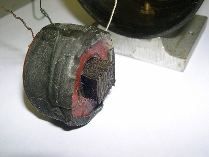
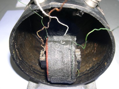
These photos show what the actual core and windings look like. It appeared like the actual windings had never been tampered with. These photos were taken shortly after I repaired the primary winding (the white cotton covered wire).
The Model C transformer is supposed to peak at 47 KC. However, my good Model C transformer was peaking at 37.0 KC and my repaired transformer was peaking at 25.6 KC! The resistance and inductance of the secondary winding of the repaired transformer was much higher than the good transformer so I started to remove wire from the repaired transformer. In total, I removed 720 turns of wire from the secondary winding and ended up with a resistance of 485 ohms and an inductance of 354 mH (close to what the good transformer measures). The repaired transformer now peaks at 35.7 KC.
There are a lot of things that don’t make very much sense. The only thing that I can assume at this time is that the core and windings of the repaired transformer were not original to the transformer. I also don’t know why E.I.S. states that their transformers peak at 47 KC when I measure a frequency of 36-39 KC. I believe the Model C transformers and the Model C-10 transformers (the plug-in units that are used in the C-10 superhet) have the same type of internal transformer.
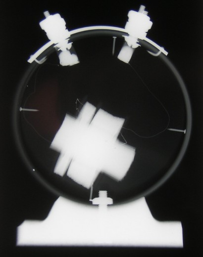
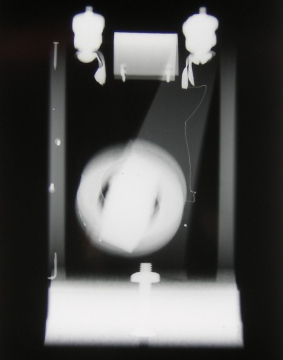
These photos show two different x-ray views of the good Leutz Model C IF transformer. One of the formica endplates has four small nails tacked into its outer circumference. When pressed into the cylindrical housing, the force of the four nail heads against the inside of the cylinder keep the endplate in place. The nails were tacked into the primary endplate on both transformers. The transformer housing was partially filled with wax before the final endplate (primary side) was pressed into place. The wax can be seen slanted on an angle in the photo on the right. The x-ray images indicated that the core and windings of the damaged transformer were probably original.
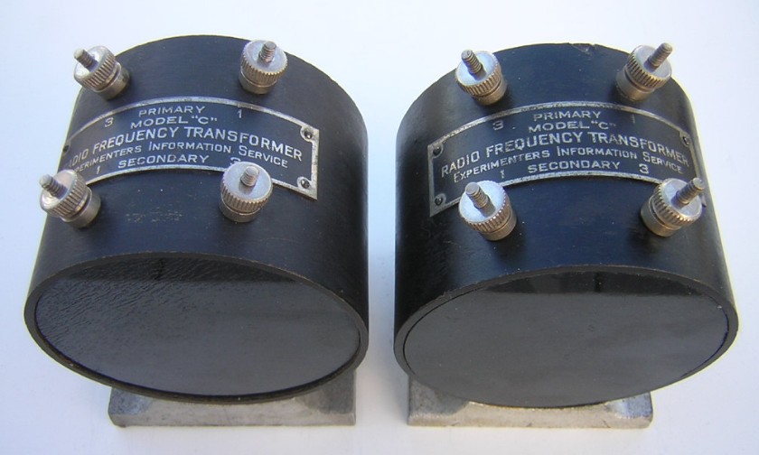
The Leutz Model C IF transformers were introduced in the summer of 1924. These transformers are fairly large and impressive, having a diameter of 3.5 inches and a height of 4.5 inches (including the terminals). The transformers are constructed with a formica housing and a massive aluminum base.
After several years of searching I was able to find a pair of the Leutz Model C transformers. One of the transformers was probably good but the other transformer had an open primary winding. Someone had attempted to repair the bad transformer by prying off one of the formica endplates (slightly damaging the transformer in the process). The secondary winding of the good transformer measured 469 ohms (349 mH) but the secondary winding of the damaged transformer measured 677 ohms (583 mH). The damaged transformer was partially filled with wax and one of the primary wires was completely missing. Under the circumstances I wasn’t sure if the internal transformer was the correct type of transformer; someone could have tried to install a replacement transformer in the Model C housing. I therefore obtained two x-ray images of the good transformer to see what the correct core and windings should look like. The x-ray images would also help me make sure that the damaged transformer was put back together correctly.
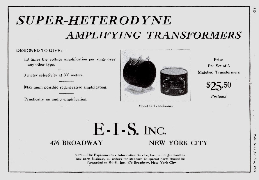
E.I.S. advertisement for the Model C transformer, as copied from the June, 1924 Radio News magazine. The advertisement may be a little misleading when it states “3 meter selectivity at 300 meters.” The frequency of 300 meters is 1000 KC, and the frequency of 303 meters (a frequency producing 3 meter selectivity) is 990.1 KC, Thus, “3 meter selectivity at 300 meters” is just a different and more complex way of saying a selectivity of 10 KC. The selectivity of a superhet is controlled by the bandwidth of the IF amplifier, and the bandwidth of the Model C transformer, by itself, is something like 40 KC (with the transformer secondary referenced to A-). The bandwidth of the entire IF amplifier chain is controlled more by the input or output coupler than by the relatively wide banded Model C transformers.
.