Supertone/Buckwalter
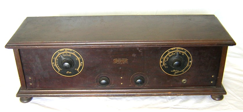
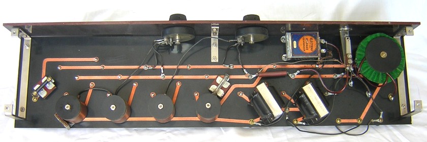
The Supertone was marketed in the late 1925 to 1926 time frame by the Buckwalter Radio Corporation. The radio is quite unique in several different ways. First and foremost is the use of a basepanel with machined grooves filled with a conductive copper material. It’s sort of like a printed circuit board but there was probably much more work involved in making this panel than its latter counterpart. In the 1920s it was illegal for most manufacturers to make a superheterodyne. Using a printed circuit to complete most of the wiring was possibly one attempt to get around the laws. The only thing a builder needed to do to finish this set was to connect a few loose wires.
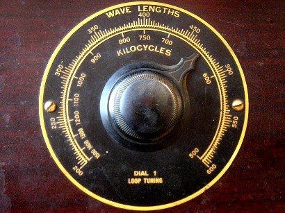
Another unique thing about this radio is the calibration of the two main tuning controls. Instead of being calibrated from 0 to 100, as most sets were at the time, the loop tuning control of the Supertone (the left dial) is calibrated in actual wavelengths and kilocycles (two scales). The oscillator tuning control (the right dial) is calibrated only in wavelengths, but there is two different scales that coincide with the two different frequencies of the oscillator that produce the desired IF. Here are a few more particulars of this set:
1. The radio looks like it operates on the standard 1920s superhet circuit. This radio is slightly different than usual in that it uses two potentiometers to control volume and no rheostats (even though the right knob on my set is labeled rheostat, it is in fact a potentiometer that goes to the IF amp).
2. The engraved front panel measures 28” long by 7” high by 3/16” thick.
3. Buckwalter oscillator coupler, IF transformers, front panel, and basepanel.
4. Remler “butterfly” tuning capacitors.
5. Jefferson audio transformers.
6. Centralab potentiometers.
7. Cutler-Hammer tube sockets.
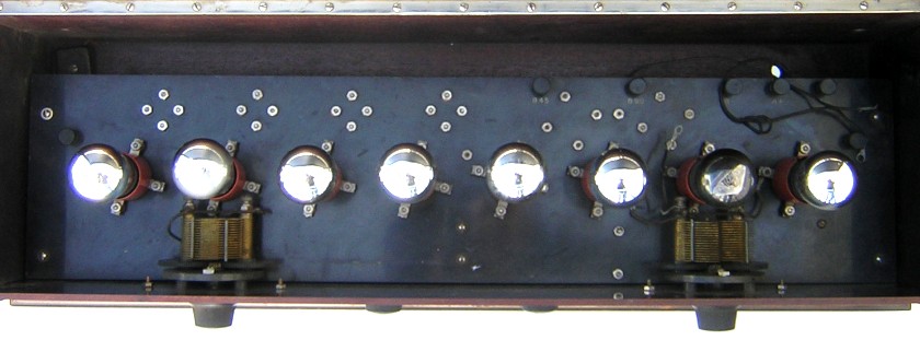
Top inside view of the Supertone. This is a very clean looking set because most of the wiring is on the bottom of the basepanel.
If you want to read more about the interesting history of the Buckwalter Supertone see an article on Nostalgia Air here.
|
Type |
Peak Freq. |
Lower 3 dB |
Upper 3 dB |
Bandwidth |
Relative gain |
Pri. ohms |
Sec. ohms |
|
#1, Filter .000482 cap |
132.4 KC |
116.2 KC |
148.4 KC |
32.2 KC |
6.5 |
34.4 |
150.8 |
|
#2 |
140.0 KC |
121.5 KC |
164.0 KC |
42.5 KC |
8.0 |
51.9 |
149.5 |
|
#3 |
138.4 KC |
107.6 KC |
171.5 KC |
63.9 KC |
3.8 |
55.3 |
143.2 |
|
#4 |
144.6 KC |
130.8 KC |
158.4 KC |
27.6 KC |
8.4 |
52.4 |
148.5 |
Notice that the wavelength scales on the two different dials are linear for wavelength divisions. This tells us that the Remler tuning capacitors are Strait Line Wavelength (SLW) capacitors. The Remler SLW tuning capacitors are the only capacitors that will work for dial calibrations of the Supertone.
The oscillator dial has two different wavelength scales because there are two different oscillator frequencies that will mix with one particular signal frequency to produce the required IF frequency. In the case of the Supertone, one oscillator frequency is 140 KC above the signal frequency and one oscillator frequency is 140 KC below the signal frequency. The two different wavelength scales on the oscillator dial should be separated by a frequency of 280 KC. However, for some unknown reason the frequency difference or span between the two scales is slightly different at different positions on the scale; at the left side of the inner scale the difference is about 263 KC, near the middle of the inner scale the difference is about 293 KC, and at the right side of the inner scale the difference is about 252 KC. Those three different frequency spans equate to IF frequencies of 126 KC, 147 KC, and 132 KC, respectively. The IF frequency is certainly not changing so there must be some other explanation. Perhaps one or both of the wavelength scales are slightly nonlinear?
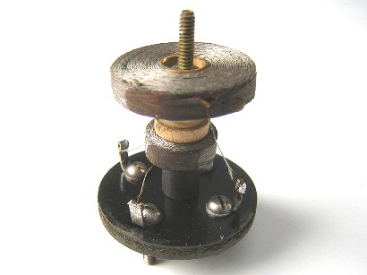
An initial ohmmeter check of the IF transformers indicated that the first transformer had an open secondary winding. This was actually a good thing because it forced me to investigate the transformer and in the process I learned something. This style of transformer is very easy to repair; simply remove one nut from the end of the transformer and remove the phenolic tube. The problem turned out to be a tiny broken wire that was very easy to solder. I ended up examining all the transformers and can report that they all look similar.
A bandpass check revealed that there was still a problem with the first transformer. The other transformers were peaking near 140 KC but the first transformer was peaking at 235 KC. The first transformer is the filter transformer and it has a .0005 mfd capacitor across the primary for tuning it to the correct frequency. The primary capacitor measured .00056 mfd and the primary inductance measured 3.24 mH (Ls=37.5 mH), which equates to a frequency of 118 KC. I put it all back together and it still didn’t work. With nothing left to try I replaced the old mica capacitor with a modern mica capacitor (.000482 mfd) and it worked! The old cap must have had some mechanical problem or leakage that the Sencore LC-53 didn’t detect.
The table below records the bandpass measurements of the transformers. The first two transformers were measured with the secondary referenced to A- and the fourth transformer was measured with the secondary referenced to A+ (the grid leak resistor and capacitor were left in place). The #3 transformer had an unusually low gain and wide bandwidth. At first I thought it was due to some type of excessive losses in the transformer, and recorded such in my notes. However, when I was writing this section on the Supertone I suddenly realized that I had probably made a mistake in measuring the transformer. What was the mistake? The bias for the #3 transformer’s secondary coil is connected to the wiper of its own potentiometer (labeled “rheostat” on the front panel) and I hadn’t noticed it. The wiper was probably set a short distance from the A- side of the potentiometer.
The loop tuning dial is calibrated in wavelengths and kilocycles.
The oscillator tuning dial has two wavelength scales.

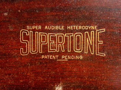
Close up view of the engraved front panel.
Inside view of the #1 IF transformer. Primary is close to terminals.
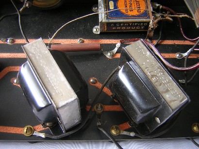
Jefferson audio transformers.
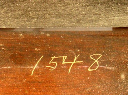
The number 1548 is engraved on the back side of the front panel.
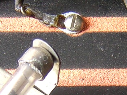
Close up view of the copper traces.
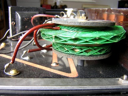
Close up side view of the oscillator coupler.
Bottom view of the chassis showing the copper channels/traces. The wiper of both potentiometers go to the IF transformers.
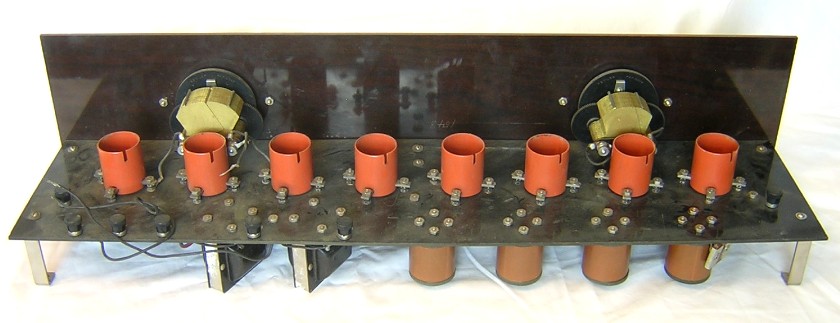
Rear angle view of the chassis. The IF transformers are at the bottom right and the audio transformers are at the bottom left.
October 30, 2020 Update:
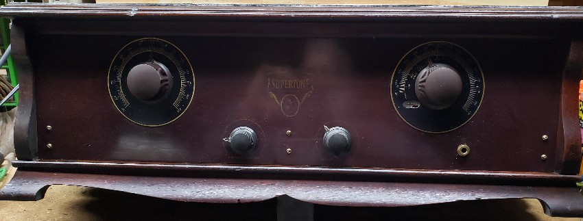
John Fritz sent me some photos of his Supertone superhet that he recently purchased at the Ron Frisbie auction in 2018. Inside the set when he purchased it there was an envelope from John Caperton, which indicates that he once owned the radio also. I asked John if I could add his photos to my site because they add much information about the Supertone superheterodyne. Thank you very much John for letting me add your photos!
This is a later set than mine (serial number 3592) and there are quite a few differences between them. First, the cabinet seen here is the standard cabinet used for the Supertone. My Supertone is the only one I’ve seen with a different cabinet. Instead of an engraved panel, John’s set has a stenciled panel with a different logo. The two large dial backplates are also a little different.
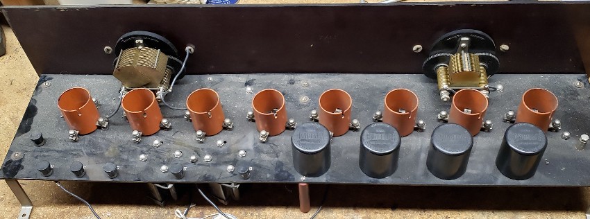
Rear chassis view of John’s Supertone. About the only thing different here between John’s set and my set is the IF transformers are mounted on top of the basepanel. The vast majority of Supertones have the IF transformers mounted on top of the basepanel. This set has the orange Cutler-Hammer tube sockets like mine, but many Supertone superhets have some type of black tube sockets. I have photos of about twenty different Supertones and it doesn’t seem to make any rhyme or reason as to what tube sockets are used, but the black tube sockets seem to be the most common.
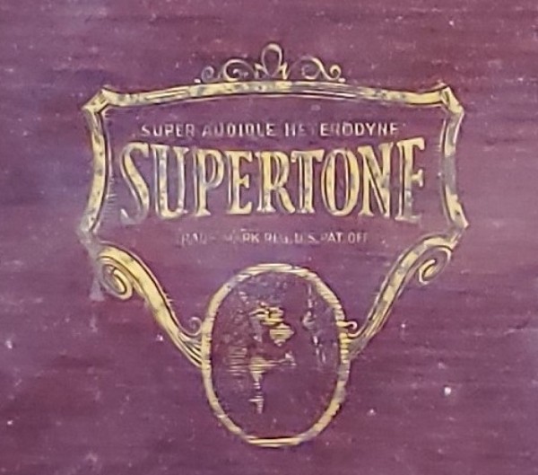
Close up view of the stenciled logo.
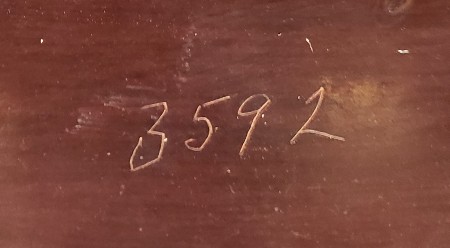
The number 3592 is engraved on the back of the front panel
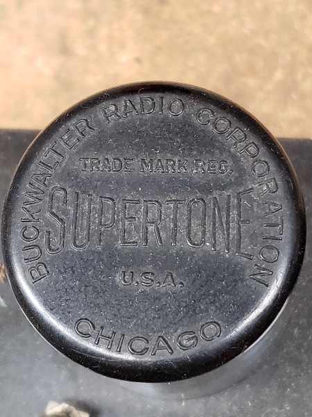
Close up view of one of the IF transformers
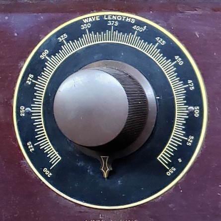
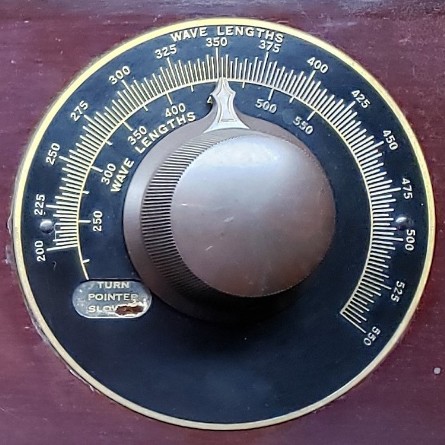
Close up views of the tuning dials. The loop tuning is on the left and oscillator tuning is on the right. These types of dials appear to be used on the later sets, along with the stenciled panels.
March 11, 2021 Update:
David Willenborg gave me permission to use his photos and information from a recent Supertone acquisition of his. David’s radio is, what I would call now, the second major version of the Supertone. My Supertone, serial number 1548, is the earliest one I am aware of. David’s, serial number 3286, appears to be the second version, and John Fritz’s, immediately above, serial number 3592, appears to be the third and last version.

Front view of David’s Supertone (version 2). The engraved panel of versions 1 and 2 are the same, which differ from the stenciled panel of version 3. The metal dial plates of versions 2 and 3 are the same, which differ from the metal dial plates of version 1. I know, I know, I’m confused too!
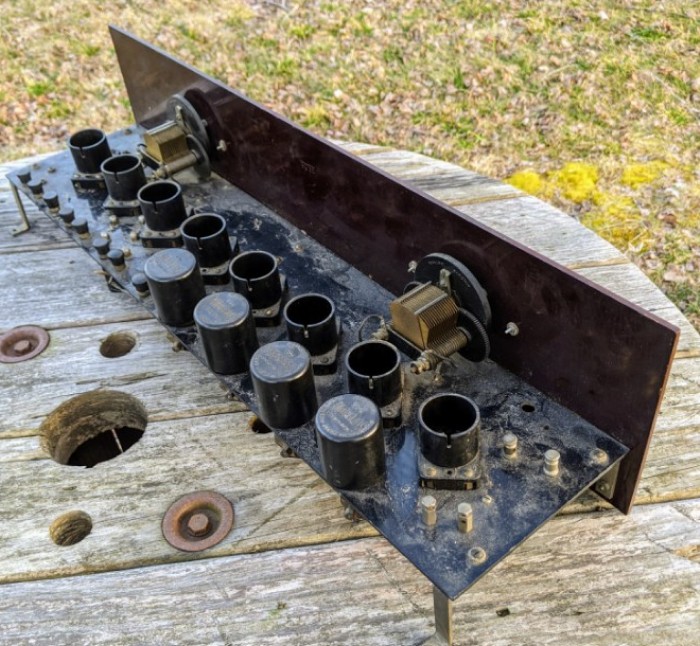
Rear chassis view of David’s Supertone. The IF transformers are mounted on top of the chassis and it uses black tube sockets. Perhaps 90% of the Supertones you come across will look just like this.
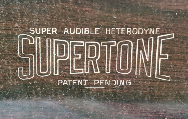
Close up view of the front panel engraving.
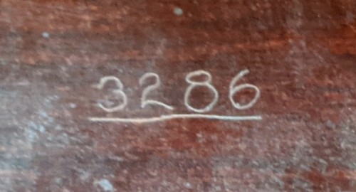
The number 3286 is engraved on the back of the front panel.

Close up view of the oscillator dial metal plate. Supertone versions 2 and 3 are identical. The Supertone version 1 oscillator plate is different in a few ways: First, the dial plate is identified as “Dial 2 Heterodyne Tuning,” and the scale goes up to a wavelength of 600. Second, the inside scale on version 1 goes down to a wavelength of 200. The inside wavelength scale on versions 2 and 3 have on oval punched hole where the number 200 should be. Apparently the inside scale heterodyne wavelength would not actually reach a wavelength of 200 and the manufacturers did not want operators trying to force the dial to go that low (or they could damage the gears on the Remler tuning capacitor). The manufacturers must have had a lot of the metal plates already made or else they could have just changed the style of the plate and not have to resort to punching an oval hole in it.
.